This test arrangement was fiddly, though it showed the possibilities.
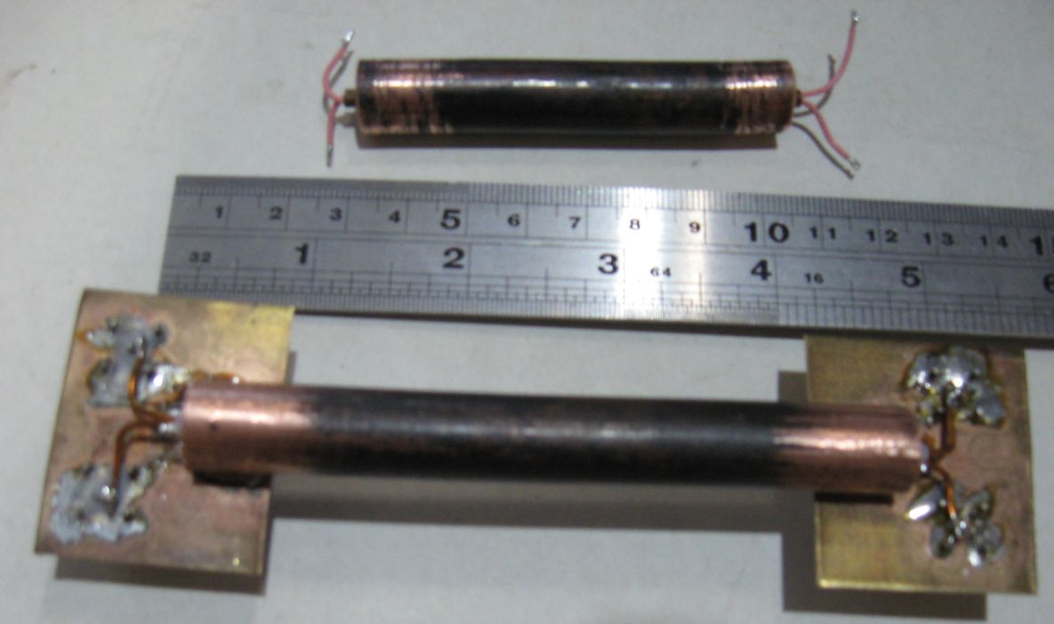
Note in the top image a smaller tube enclosing the pink wires.
This is known as a Coupling Enhanser.
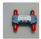
Below is an example of "Sage Labs Wireline(R)". 200mW amp vintage 1980.
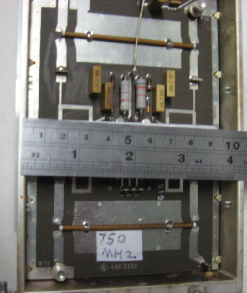
Now with an easier test jig.
Way too much coupling. Feed is lower left. About 10db down on Top right.
No notch on lower right port.
next
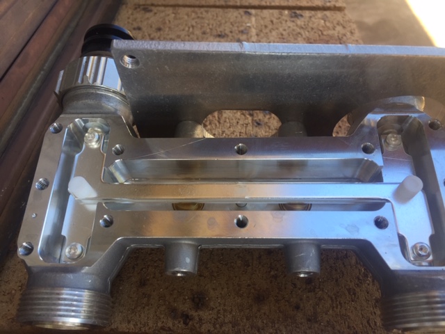
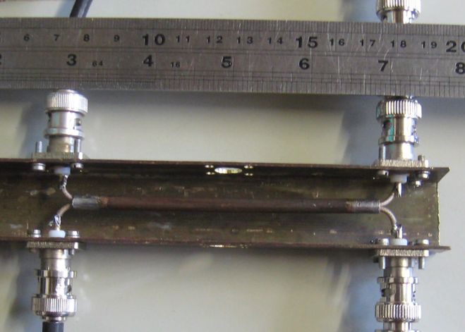
Flat broadside striplines, two pieces of PCB air between, adjustable.
Dielectric thickness I've spotted 31, 5, 31 mil, thats 6,1,6 units.
That's close to the actual hybrid I have for 225MHz, 10, 1.4, 10mm.
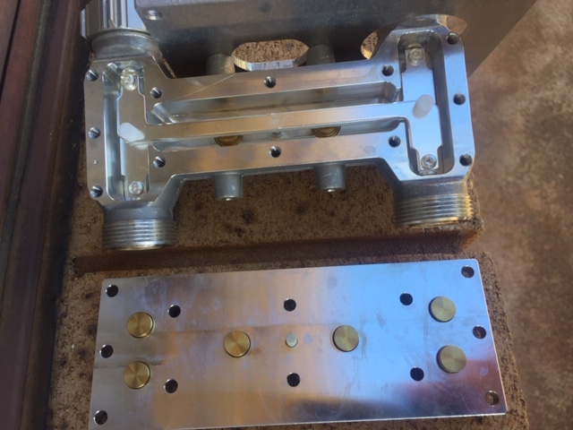
I've built one here, but thus far, not good enough, no notch, poor RL.
I do put a top shield on for testing. RL -10db, terminator port -12db, P1 -3.7db, P2 -4.0db.
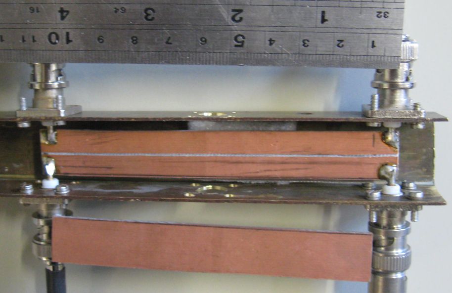
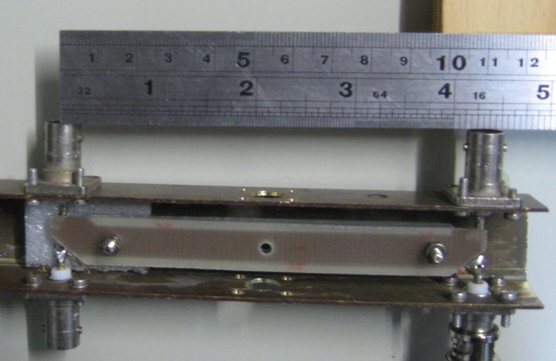
Another try, 15mm wide PCB and a saw cut down the middle. A piece below
supported by the foam, another for atop.
OK then, this is not useful. Yes we get coupling, 400 to 700MHz
but the input RL is poor -10db and the terminator port has about -10db signal
and no sign of being any lower with perfect loads on the two output ports.
I wanted to know the secrets. This is way too hard.
So I bought one on eBay!
Now I can concentrate on the antenna.
I'd love to read this book: R. K. Mongia et. al. RF and Microwave Coupled-Line Circuits
At the end of this article below are pictures, yes a picture speak a thousand words.
https://www.hindawi.com/journals/ijap/2016/7964528/
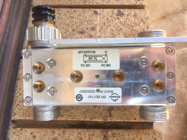
A commercial example, did I miss the adjuster screws?
Thanks Tim VK2ZTH.