 loops3.jpg from www.repeater-builder.com
Compared to: 70cm with 5 to 10MHz or 1-2% freq spacing, and 6m with 1MHz 2% spacing.
loops3.jpg from www.repeater-builder.com
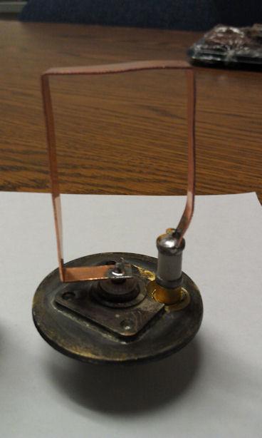
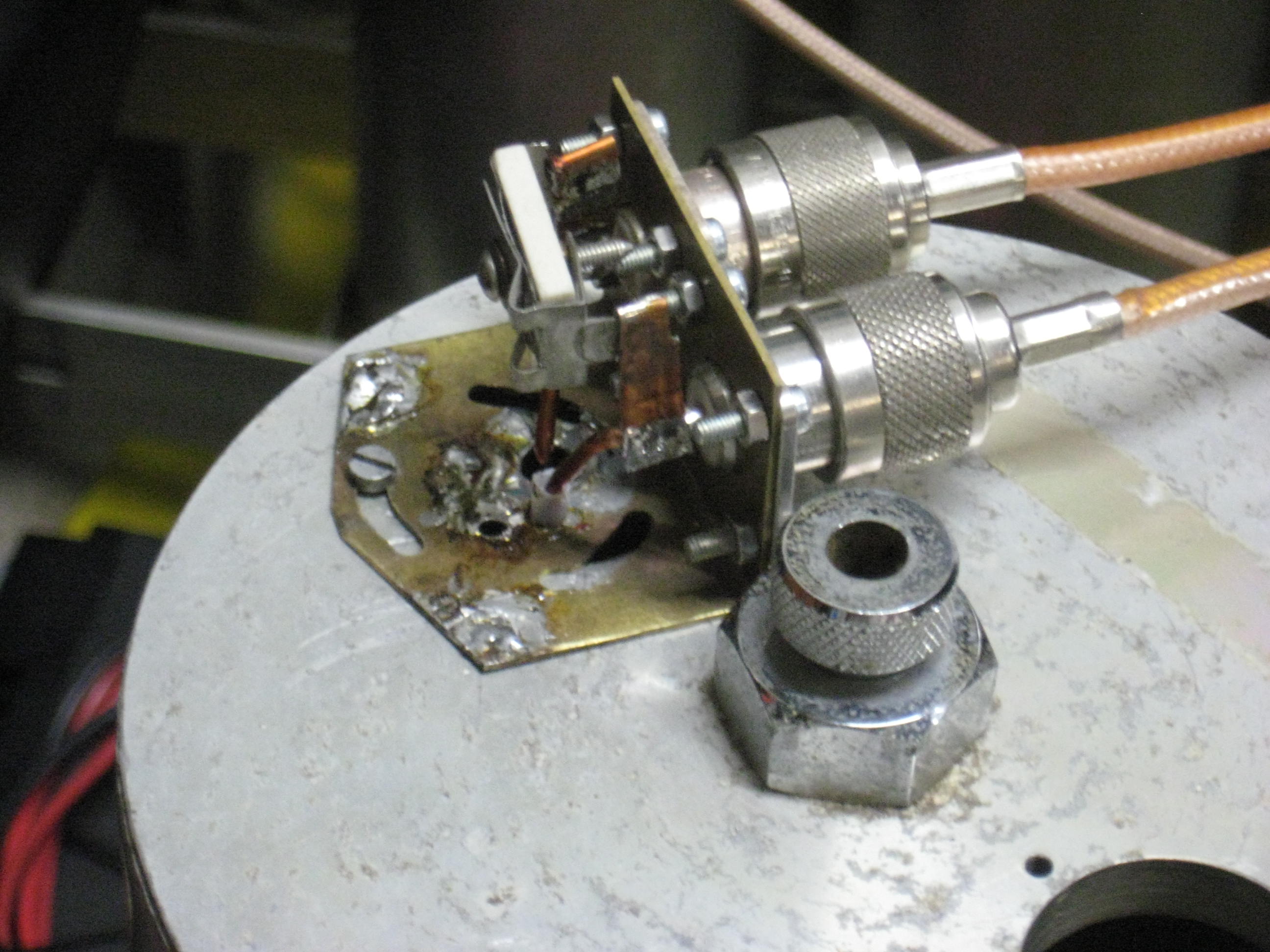
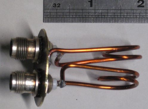
 my photo IMG_3116.JPG
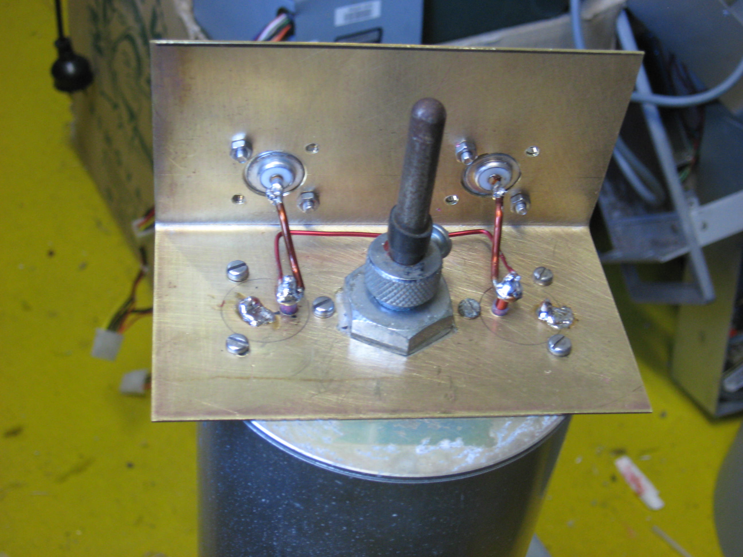
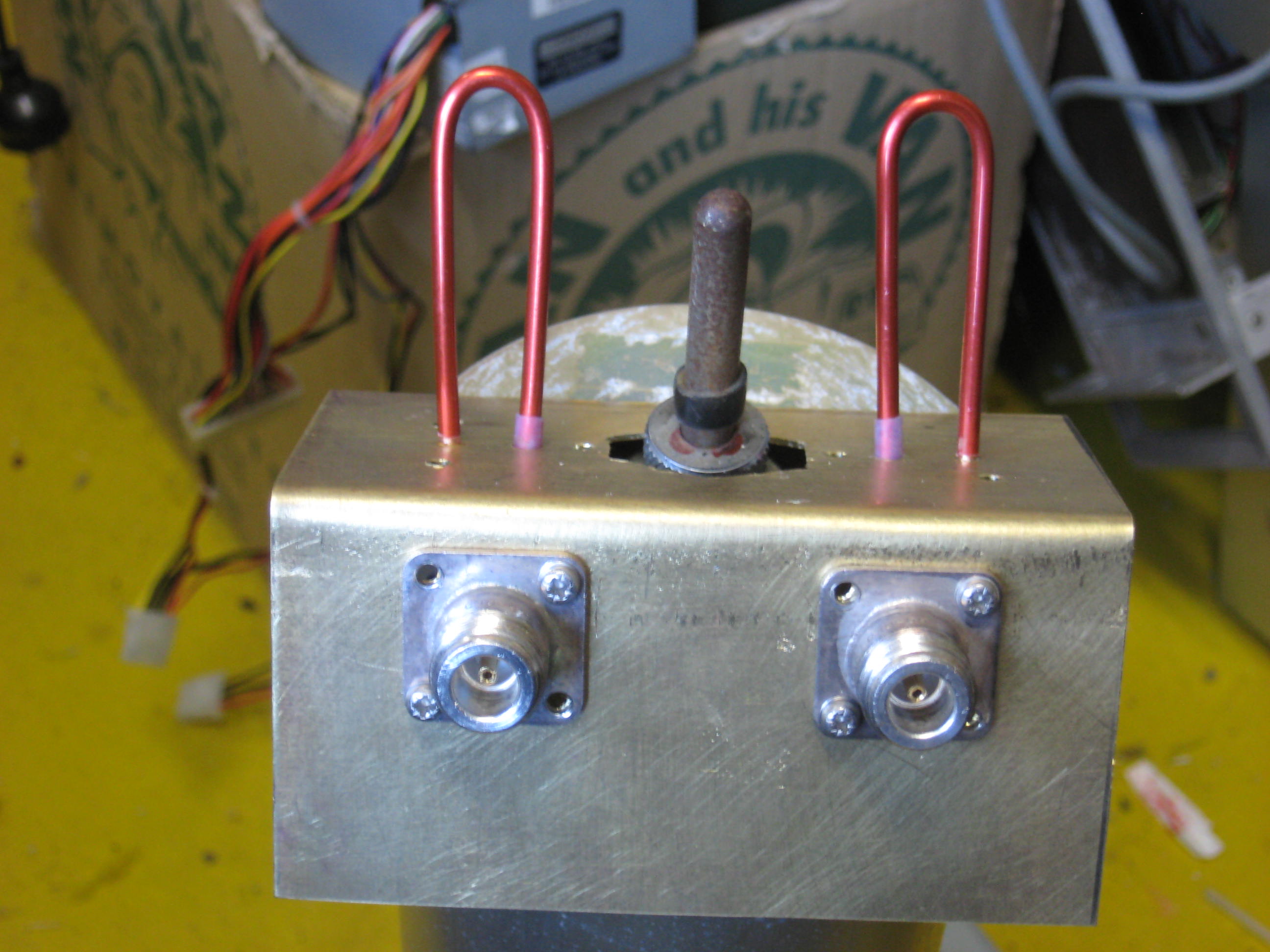 my photo IMG_3117.JPG
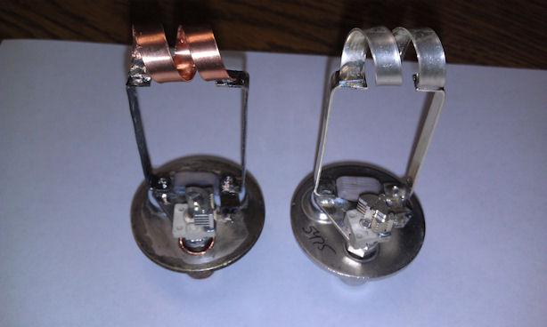
Note, none of the commercial units I've seen use the
couple a bit of energy from one connector to the other
approach.
Because, 3MHz is a much more common frequency spacing on the 150 to 180MHz band.
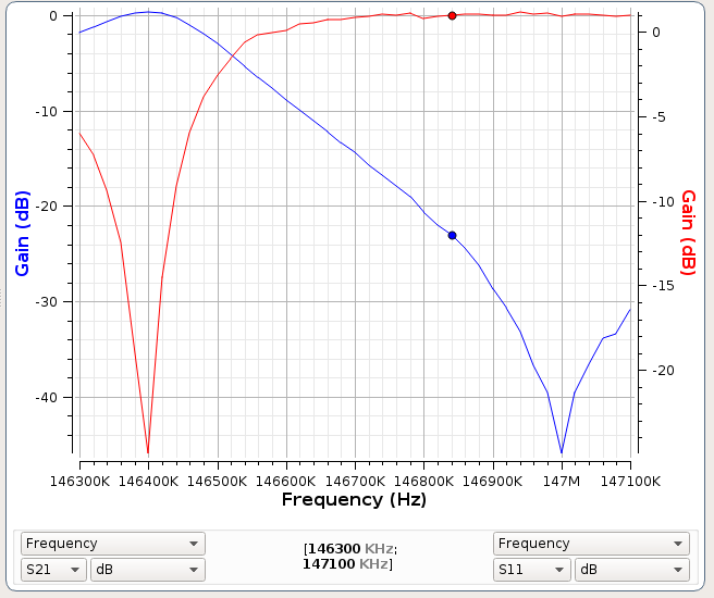
 HIGH loops21.jpg from www.repeater-builder.com
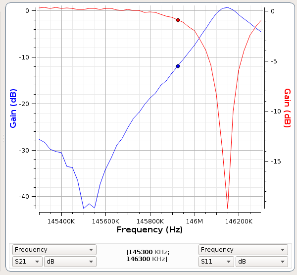
 LOW loops13.jpg from www.repeater-builder.com
Note the extra inductance out of the main magnetic field.
See: http://www.repeater-builder.com/projects/coupling-loop-research.html
From this web page by Kevin K. Custer W3KKC, Jeff WN3A used a 6 inch cavity for his tests:
(S11) - (S22) return loss and notch depth.
Factory Low-Pass: 22/25 dB return loss, 38.3 dB notch depth
W3KKC Low-Pass: 21/26 dB return loss, 39.2 dB notch depth
Factory High-Pass: 25/22 dB return loss, 39.9 dB notch depth
W3KKC High-Pass: 26/22 dB return loss, 40.7 dB notch depth
====
So we hams can build them as good as commercial too.
From their measurements, the performance is near 10db better than the serial loop and "N" Tee. (resistance in the T pin and socket I bett)
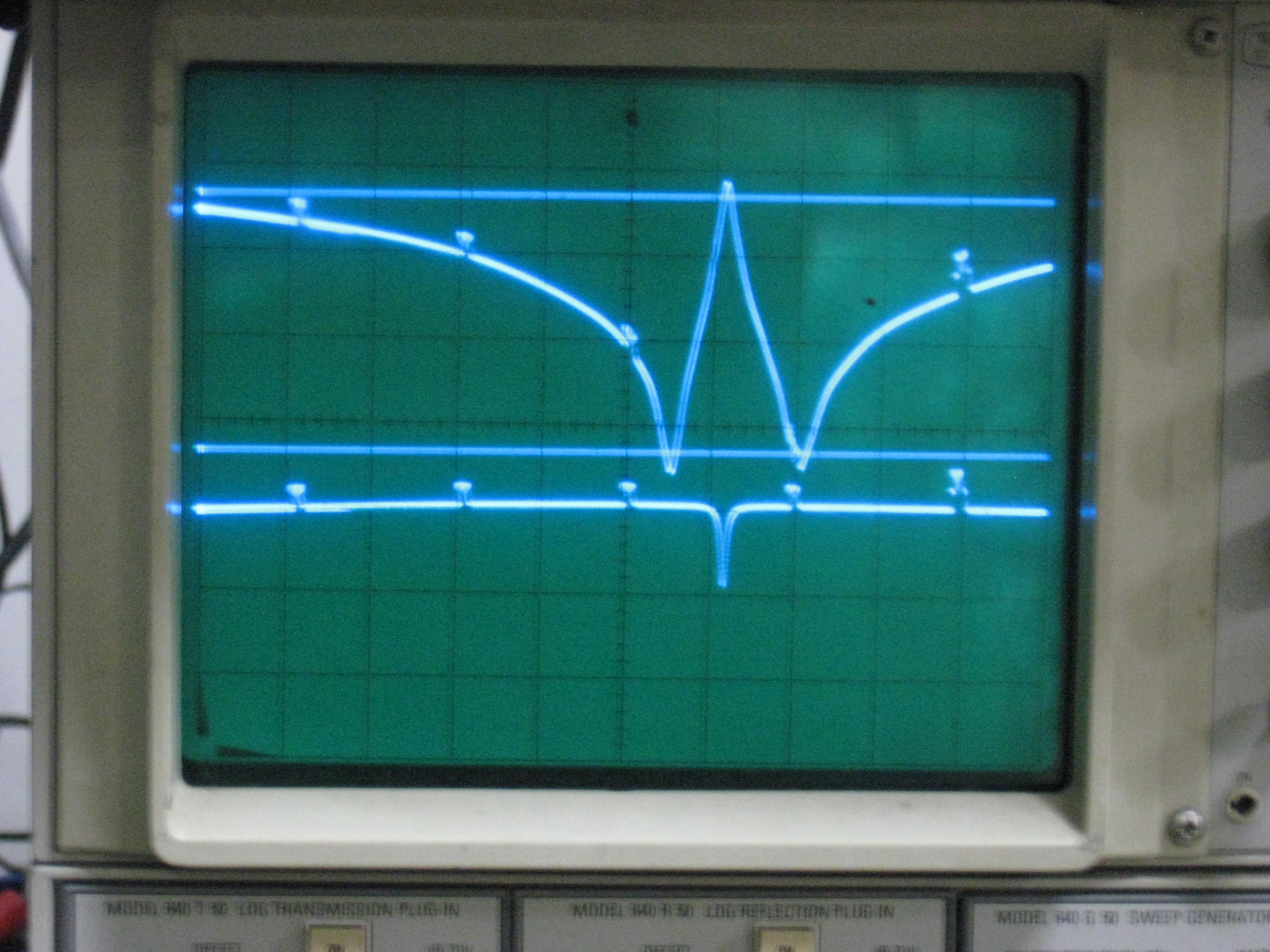
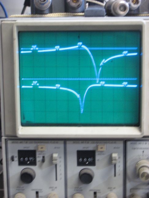
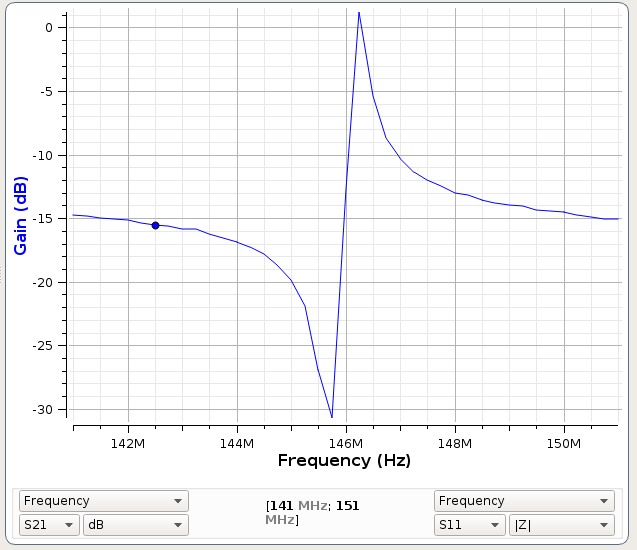
Here we get two notches (about 2MHz apart) with a pass between them. So we adjust the pass to be closer (600KHz) to a notch, either higher or lower, depending if this cavity is in the Rx or the Tx chain. See IMG_3250.JPG below.
Another advantage At the notch frequency, the impedance at the cavity is VERY low so we can use a 1/4 wave (or 3/4) line to it and present a HIGH impedance at the antenna "T". Makes our life easy with separating the Tx and Rx signals. No need for a circulator.
Disadvantage No "out of band" rejection.
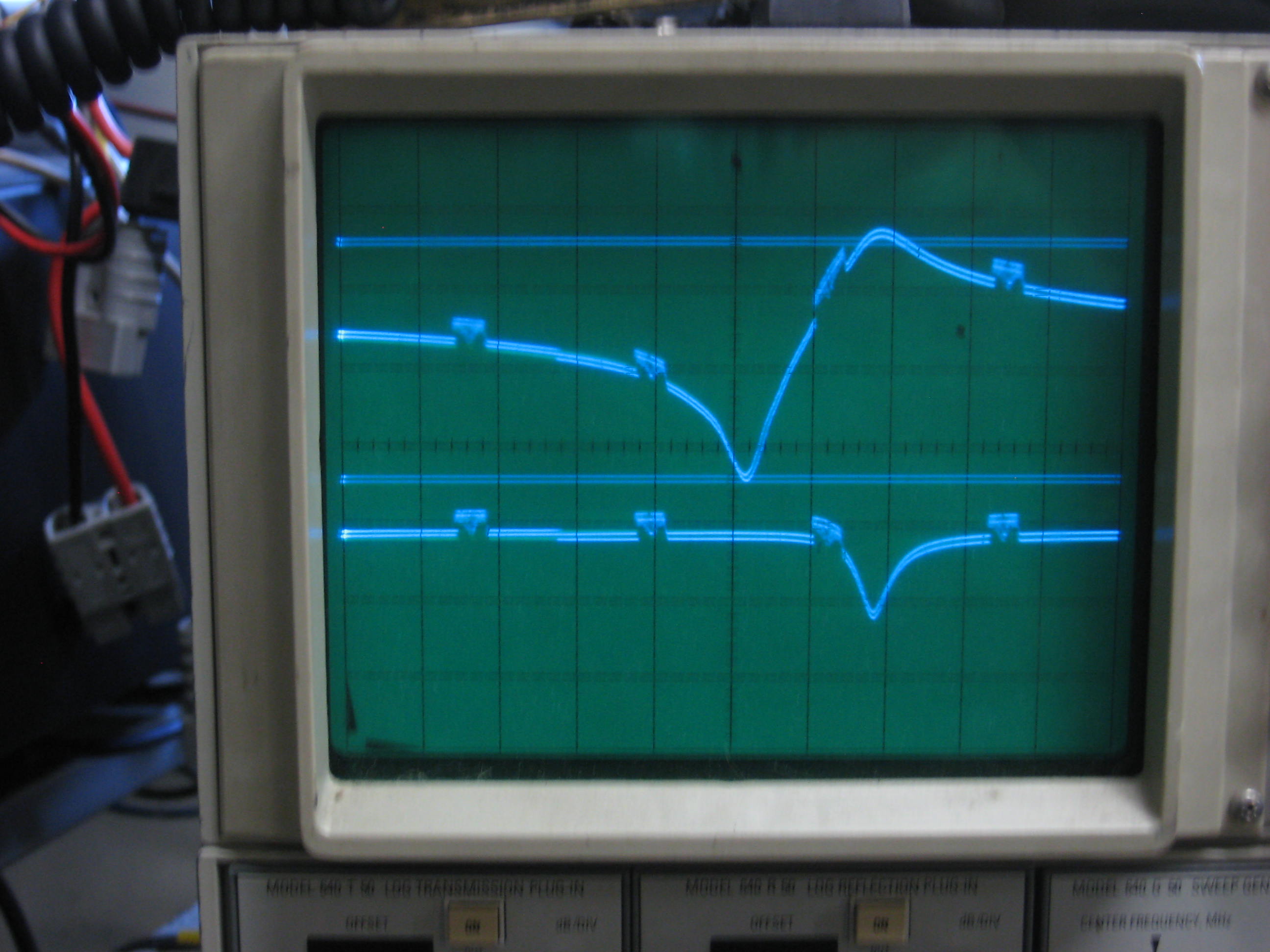
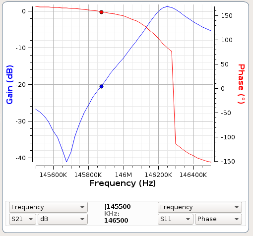
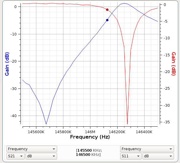
Here we have only one pass and one notch and some "out of band" rejection.
Only one resonant circuit, the cavity.
The pass/notch sense can be swapped by using capacitance instead of inductance as seen in my above picture.
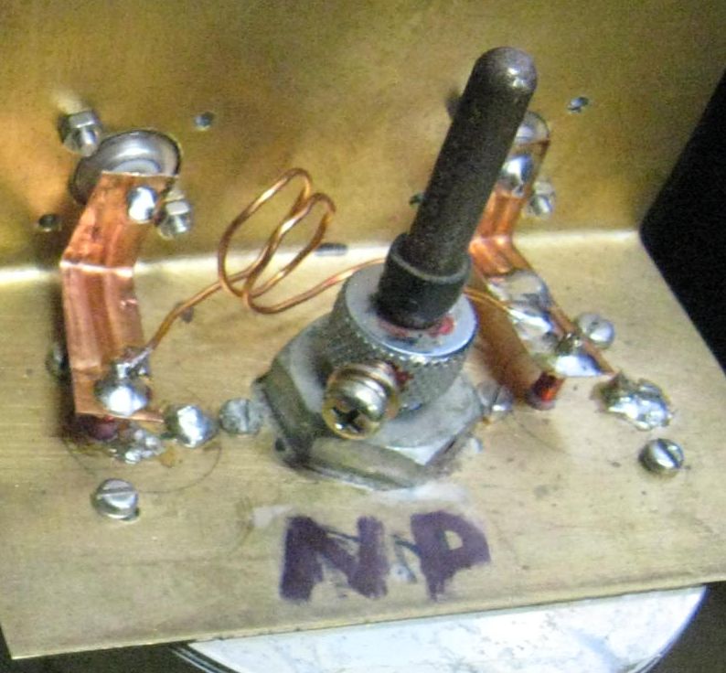
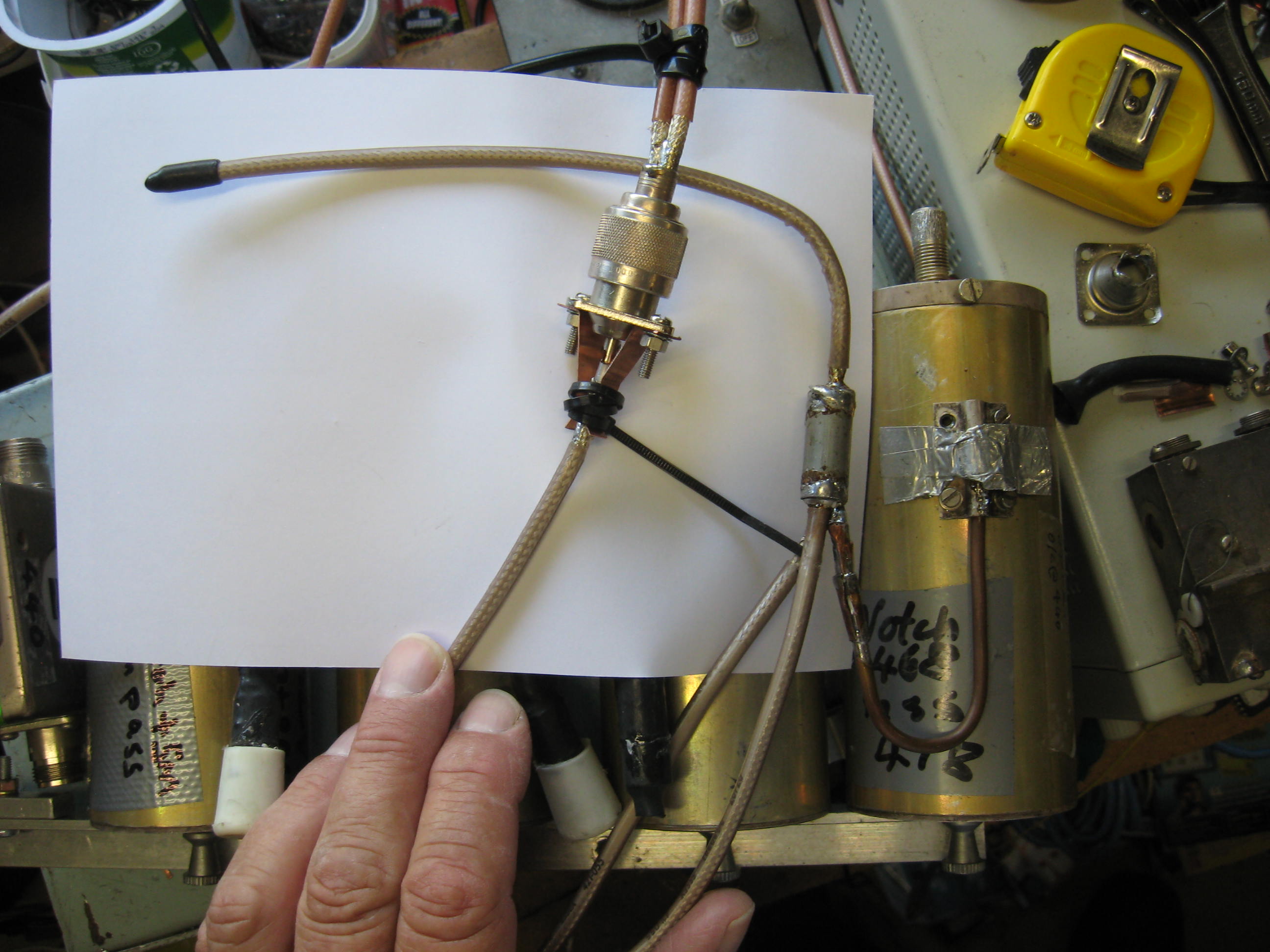
There is much innovation here in ham literature. But, very little in-depth discussion. Eg. the wire size used in the loops, does it matter? Yes, thicker wire or strip has lower loss but but but, lower self (or stray) inductance. So don't just jump in and thicken up the wire size when refurbishing.
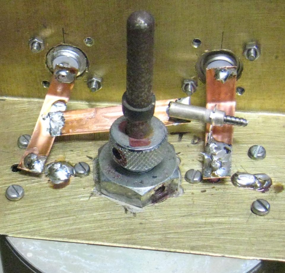
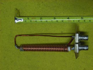
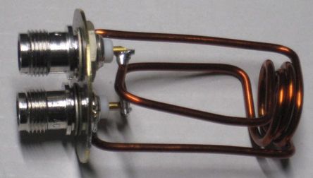
Note also, one can swap the phase of the loops as below.
Note the much higher inductance used compared to IMG_3116.JPG above.
Conventional phase: Both loop active leads come from near the inner. Here LHS one is not.
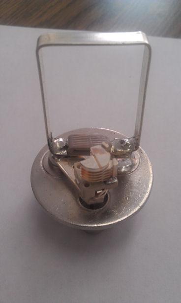
 IMG_3222a.JPG from me
 IMG_3224a.JPG from me
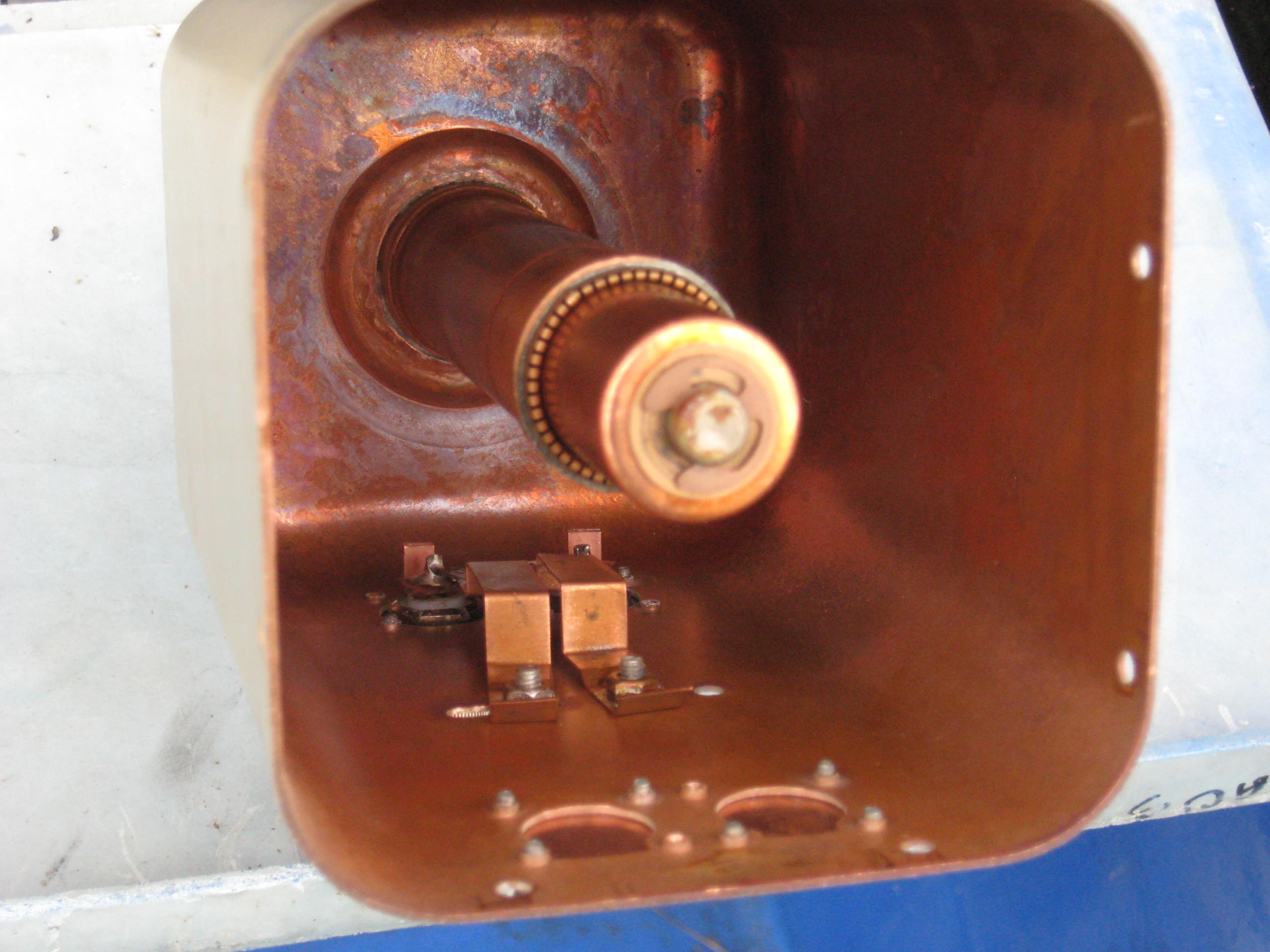
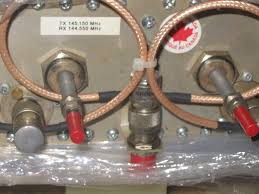
What about placing the two loops inside the cavity close to one-another
such that there is significant magnetic coupling?
Yes this works. At UHF in 4" square cans, I've got 5MHz spacing. Note the slots Motorola provided.
But to swap the pass/notch to notch/pass is very problematic due to the
magnetic field not being uniform either up and down or in and out.
I've figured a way!! See the 2m example in basics.html
 my photo IMG_3242.JPG>
Disadvantages: As a first can after the antenna "T", we have problems
because the impedance at the can is not an easy very LOW impedance so we have
to measure the impedance and calculate the correct coax length that will
present a HIGH impedance at the antenna "T". I suspect our predecessors had
zillions of coax male-to-mail and female-to-female joiners and/or a length
adjustable coax line.
Eg. General Radio P/n 874-LK20 CONSTANT IMPEDANCE ADJUSTABLE LINE 20cm
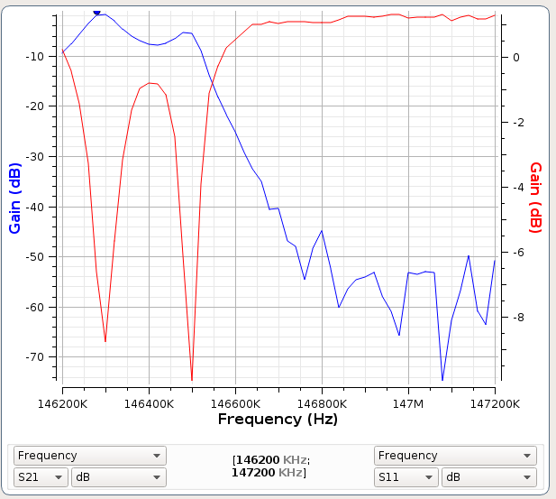
Here again we have two notches and a pass...
 IMG_3251.JPG from me
 IMG_3250.JPG from me
35db notch is not bad but the RL could be better. First attempt.
This 6" cavity has no main tuning yet. Was 70MHz. I'll cut it to 148.2MHz and
put an insulated sleeve in the inner, protruding to bring the freq. down.
A fiberglass rod as pusher.
The pictures loops21.jpg and loops13.jpg above show best practice.
Again see: http://www.repeater-builder.com/projects/coupling-loop-research.html
Advantage: Hi Z at notch. Therefore use 1/2 wave line to antenna "T".
Disadvantage: Poor "out of band" rejection.
 RIMG0003.JPG today 2/6/17
 IMG_3713.JPG today 5/6/17
1MHz markers, 35db notch, not bad. Lower trace Return Loss
But cuts way too much cavity magnetic flux.
IMG_3720b.JPG cuts way too little cavity flux, note the orientation of the two turn coil 11/3/18
IMG_3723b.JPG this looks good, 2x 80mm pieces of 1/4" hardline as capacitor, resonates at 130MHz out of cavity 11/3/18
The 34mm cavity probe hole size makes it hard to have two "N" connectors. They need 45mm.
The set I'm working on, a 3/4 wave 70cm set, note the small coupling loop.
TNC connectors, can space 18mm apart
35db notch, just as good as the Repeater-Builder coupling-loop-research ones.
Still tricky to adjust, twisting the assy, need more L in the one turn coil at RHS. Fixed below, two turns, same wire.
Spacing, notch to pass, adjustment a breeze.
pass Upper
pass Lower
=================== Series loop again ===========================
Below a series loop using hardline as capacitor.
Heliax in and out to avoid a "T" piece.
Very unwheeldy but about 6db better
than my "T" being two coaxes into a plug.
Both plug and socket have gold plated pins.
 IMG_3709can.JPG
 2m Res-Lok
 IMG_3228.JPG
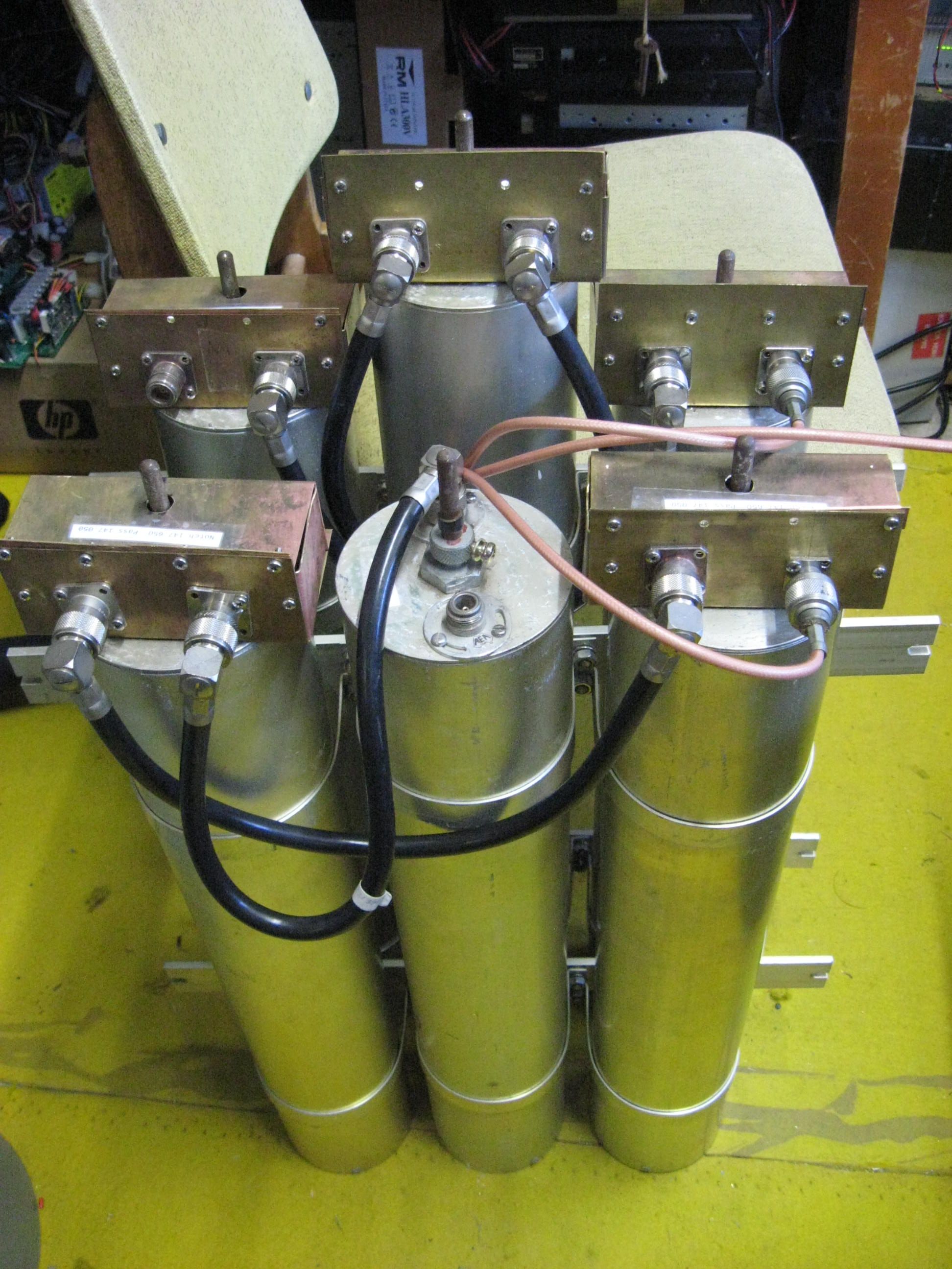
1/4 wave lines to 1st cans, series loop type. Next two cans, two loop types as per
IMG_3222a.JPG and IMG_3224a.JPG.
Antenna "T" hidden, a plug on the LHS ends of the two teflon coaxes plugged into the RHS brass boxes.
4" cans are barely adequate. Go 6" or larger.
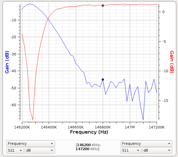
 Pass then Notch, 2x 195mm x 2mm wire 14mm ID coil
 PocketVNA scan, 6" can.
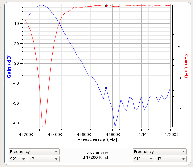
============= Now Notch then Pass ================
 Notch then pass 2x 205mm x 2mm wire 14mm ID coil
 PocketVNA scan, 6" can.
So easy to fabricate and adjust.
Out of band rejection, 13 to 16db for pass then notch, 16db to 20db for notch then pass.
Notch then pass 2x 205mm x 2mm wire 14mm ID coil
This gives us a hint to the line lengths needed to the antenna Tee.
Here is the scan of two cavities inter-connected with a short cable 300mm RG58.
They were both tuned for a Pass at 146.3MHz and Notch at 146.9MHz.
Now a long cable 1240mm, RG058 SAXTON 1591F.
Note, the PocketVNA's S21 detector gets noisy at -45db as you see here.
Cable 420mm RG58
Note here, I didn't retune the cavities, I just changed the inter-connect cable.