| To have a duplexer designed, engineered and custom-built
to your specifications which is rugged enough to withstand shipping via UPS, e-mail me (Jim) here: "jvpoll at dallas dot net". |
|
Low-band VHF Hybrid Ring Heliax Duplexer Performance on 6 Meters
Why a Hybrid Ring Duplexer? Two words: "Band pass". Utilizing a notch stub in a Hybrid Ring configuration yields a band pass function rather than the more usual notch or 'reject' function.
The graphic above shows the following "S21" S-Parameter sweeps for a 1 5/8" Heliax Duplexer using only 4 Heliax stubs:
This HR duplexer, modelled using
 Q:
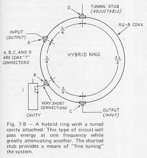
What is a Hybrid Ring?
Q:
What is a Hybrid Ring?
A: A 'Hybrid Ring' is an electrically circular configuration of coaxial cable that posseses certain electrical properties that enable electrical isolation to be achieved in a different manner than that achieved using the usual band-pass or band-reject circuit configurations.
A Hybrid Ring circuit configuration is used to turn a notch element into a bandpass element through the magic of signal cancellation; the total length around the ring is 6/4 (or 1 and 1/2) wavelengths total. Now note the difference between the two 'path lengths' between the INPUT and OUPUT points: a) 1/2 wavelength going counter-clockwise past the CAVITY and b) 1 wavelength going clockwise around the other way; if one sends a signal into the port labelled INPUT nearly total signal cancellation occurs at the port labelled OUPUT (assuming the CAVITY or stub is not present or active) because of the total path length difference is 1/2 wavelength, and signals that are 1/2 wavelength (or 180 degrees) out of phase cancel (assuming equal amplitudes).
Now note the placement of the the 'cavity' (or notch stub) located midway
between two points marked INPUT and OUTPUT; at the frequency the stub is
tuned to, the 1/2 lamda 'path' is effectively 'shut off' by the short
created by the notch stub between those two lengths of 1/4 wavelength cable;
the short created by the stub also becomes effectively an open through
the 1/4 wavelength cable at the INPUT and OUTPUT ports, and the 'signal
cancellation' we had moments ago now goes away; the Hybrid Ring now exhibits
a 'band pass' characteristic at the frequency the CAVITY (or stub in our
case) is tuned to.
 1)
BR- Band Reject, also known as 'Notch Duplexer' built using tuned/resonant
elements that 'notch' out one particular frequency in the receive and transmit
legs.
1)
BR- Band Reject, also known as 'Notch Duplexer' built using tuned/resonant
elements that 'notch' out one particular frequency in the receive and transmit
legs.
A Band Reject (BR) type duplexer means that deep attenuation 'notches' are provided for 1) receiver protection (from the transmitter's output) as well as 2) transmitter noise (at the receive frequency). The attenuation of 'out of band' signals is less with a BR design than that achievable with a BP design (although there is *some* attenuation of 'out of band' signals with a BR design).
The benefits of BR duplexer designs are:
2a) BP - Band Pass, built using tuned/resonant elements which 'pass' one particular frequency in the transmit and receive legs.
BP duplexers are especially suitable in frequency crowded areas and provide additional rejection of in-band and out-of-band signals. Although BP duplexers generally have a slightly higher IL than BR style duplexers often times it is worth the slight 'cost' of the additional IL for the protection afforded the receiver and the filtering done to the transmitter; sometimes the 'path' into the transmitter is a source of transmitter intermodulation with other nearby transmitters so the benefit of a BP extends there as well.
2b) BP - Band Pass, as realized in a Hybrid Ring configuration using tuned/resonant elements which 'notch' one particular frequency in the Hybrid Rings in the transmit and receive legs.
The image to the left shows how the four band pass Hybrid Rings (two for transmit and two for receive) are connected for use in a HR bandpass duplexer.
The length of cable to the common antenna port, although not shown, would be a 1/4 wavelength of cable from each Hybrid Ring to a common point (like a UHF or BNC 'Tee" connector) known as the Antenna Port.
3) BPBR - Band Pass Band Reject, a combination of the above
4) HPLP - High Pass Low Pass, built using high pass fitlers and low pass filters.
Sweep frequency range 45 MHz to 60 MHz of the 4-stub HR Duplexer encompassing
TV CH 2 (54 - 60 MHz). For this sweep the following parameters were measured:
Note the amount of attenuation offered by the Hybrid Ring Duplexer
over a broad range of frequencies compared to the Notch duplexer shown
below; this is the major feature of this design.
Sweep frequency range 45 MHz to 60 MHz of a 6-stub Notch Duplexer encompassing
TV CH 2 (54 - 60 MHz). For this sweep the following parameters were measured:
It is obvious that the BR (band reject) or Notchs only act to notch
basically two frequencies: the transmit and receive frequencies.
-- Duplexer Specs --
Duplexer performance can be measured and quantified with three main figures:
1) Insertion Loss, measured as an S21 or S31 value at the Receive and Transmit frequencies respectively,
2) Isolation (TX to RX Isolation) measured as an S23 value and
3) Return Loss measured as S11, S22 and S33 values at the Antenna, Receive and Transmit port respectively.Insertion Loss
This value is the measured loss in the pass band of the receiver (or transmitter) leg between the receiver (or transmitter) port and the antenna port at the respective receive (or transmit) frequency. This value represents the small amount of attenuation or 'insertion loss' that results when the duplexer is placed in-line between the receiver or transmitter.The following chart shows the reduction in transmit power due to the Insertion Loss of the duplexer. A 1 MHz split,
90 dB notch duplexer, properly designed and built, paying particular attention to the key physical parameters that determine the recovery from the 'deep' attenuation notch are capable of achieving insertion loss values of around 1 dB. In the 3rd generation design this is accomplished using microstrip techniques.
Isolation
This value is the measured isolation between the Transmit port (port 3) and the Receive port (port 2). In S Parameter parlance on this web page, this is the S23 value.The 'Isolation' figure reveals the amount of isolation between the transmitter and the receiver. Two such 'values' for isolation exist for every duplexer, one for the receive frequency and one for the transmit frequency.
Return Loss (VSWR)
I prefer using the term return loss to SWR or VSWR since so very few of us actually measure 'VSWR' directly; usually, we measure return loss using a directional coupler (or a directional Watt meter like the famous Bird series) and convert this figure to VSWR using the usual, well-established formulas and via HP's APPCAD utility or the venerable HP VSWR "Reflectometer" slide rule.To that end, the following close relationships exist between Return Loss and VSWR:
Return Loss VSWR 14 dB 1.5:1 18 dB 1.3:1 21 dB 1.2:1 26 dB 1.1:1 The return loss value, directly related to the VSWR (Voltage Standing Wave Ratio), is a measure of the match the duplexer presents to the transmitter, the receiver, and even the antenna. Below is the sweep obtained during modeling of a Heliax duplexer design. Practical experience shows that comparable results can be achieved when building the Heliax duplexer - Return Loss values better than 20 dB translating to a VSWR of around 1.2:1 can be achieved with proper design and tuning.
Sweep frequency range 51.5 MHz to 53.5 MHz of the 4-stub HR Duplexer. For this sweep the following parameters were measured:
S11, Red, Antenna leg RL performance. S22, Yellow, Receive leg RL performance. S33, Green, Transmit leg RL performance.
Commercial product - comparison
For comparative purposes, via www.repeater-builder.com/rbtip/duplexerspecs.html we can see what the key performance parameters are for a commercial DB-4032 (an 8-can helical resonator VHF low-band duplexer):---------------------------------------
Type: 8 helical resonators, bandreject
Minimum freq. spacing 0.5 MHz
Insertion loss 2.0 dB
Max. continuous power 150 watts
Tx noise supp. at Rx freq. 80 dB
Rx isolation at Tx freq. 80 dB
VSWR 1.5:1
---------------------------------------
-- History --
The history of duplexer design for Six Meters using Heliax stubs dates back to the late eighties when I began several years of low-level research involving the mathematical analysis, simulation and 'bench work' on shorted Heliax stubs; work that finally culminated in a proof-of-concept prototype design of a notch duplexer in about '91 which was constructed out of1 1/4" Heliax.
Duplexer design, website issues, or to have a duplexer built for use on your VHF low-band commercial (30 - 50 MHz ) repeater or for the 6M Amateur band e-mail Jim (call sign: WB5WPA) at "jvpoll at dallas -dot- net" (Be sure to remove the at and -dot- and spaces and replace as required).
* * * * * * * * * * * * * * * * * * * Copyright Notice: The author would like to retain any and all rights to images, text or other creative works (including pictures, sketches, hand or machine drawn art) appearing on this page. Also, should derivative works be created based on this work it is asked that reference or cite be made to same in the 'references' section of said derivative works.