 http://www.mixw.co.uk/CAVITY/cavity.htm
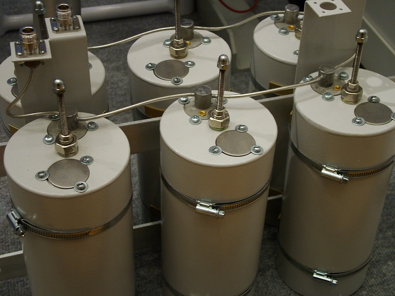
Note, none of these commercial units use the couple a bit of energy from one connector to the other approach. Note the gold trimmer. 70cm, 1% freq spacing.
http://www.mixw.co.uk/CAVITY/cavity.htm
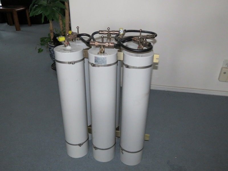
A $2000AU TeleWave TPRD-1556 2m 5" dia. set in Italy for sale on eBay.
A picture speaks a THOUSAND words. eg. cm-1008.pdf Q series. Files:
The Telewave specs here:
http://www.unixservice.com.au/hamradio/repeaters/duplexers/TWDS-6025.pdf

http://www.vk6uu.id.au/cavity-filters.html
http://www.repeater-builder.com/antenna/pdf/ve2azx-duplexerinfo.pdf
http://www.unixservice.com.au/hamradio/repeaters/duplexers/cm-1008.pdf
http://www.unixservice.com.au/hamradio/repeaters/duplexers/cm-1009.pdf
http://www.unixservice.com.au/hamradio/repeaters/duplexers/cm-1010-mr-series-mobile-duplexer-tuning.pdf
http://www.unixservice.com.au/hamradio/repeaters/duplexers/db-4048-2.jpg
http://www.unixservice.com.au/hamradio/repeaters/duplexers/design-of-high-isolation-duplexers.pdf
http://www.unixservice.com.au/hamradio/repeaters/duplexers/duplexer-loop-tests-ve2azx.pdf
http://www.unixservice.com.au/hamradio/repeaters/duplexers/emr-corp-antenna-duplexers.pdf
http://www.unixservice.com.au/hamradio/repeaters/duplexers/fp-fr-fq-series-tuning.pdf
http://www.unixservice.com.au/hamradio/repeaters/duplexers/q202-208-218-tuning.pdf
http://www.unixservice.com.au/hamradio/repeaters/duplexers/q2330e-duplexer-tuning.pdf
http://www.unixservice.com.au/hamradio/repeaters/duplexers/seits-duplexer-theory-and-tuning.pdf
http://www.unixservice.com.au/hamradio/repeaters/duplexers/seits-duplexer-theory-and-tuning.pdf.1
http://www.unixservice.com.au/hamradio/repeaters/duplexers/telewave-tprd-1554-and-1556.pdf
http://www.unixservice.com.au/hamradio/repeaters/duplexers/tx-rx-instruction-manual-vari-notch-duplexers-with-6-inch-cavities.pdf
http://www.unixservice.com.au/hamradio/repeaters/duplexers/tx-rx-technical-notes-on-duplexer-problems-and-remedies.pdf
http://www.unixservice.com.au/hamradio/repeaters/duplexers/tx-rx-t-pass-expandable-cavity-multicoupler-cavity-system.pdf
http://www.unixservice.com.au/hamradio/repeaters/duplexers/w1gan-duplexer.pdf
http://www.unixservice.com.au/hamradio/repeaters/duplexers/w2eup-hybrid-ring-duplexer.pdf
telewave-tprd-1554-and-1556.pdf
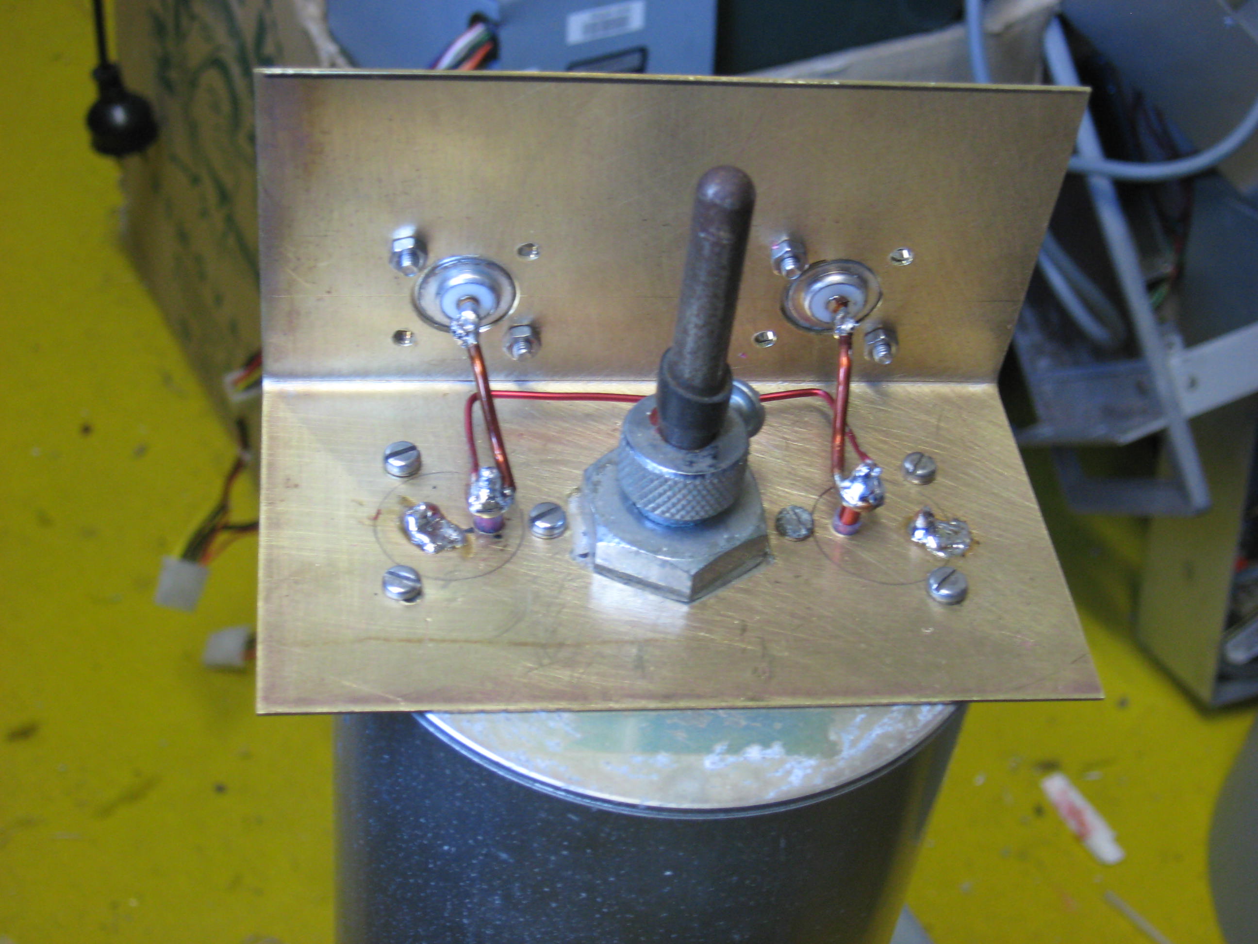
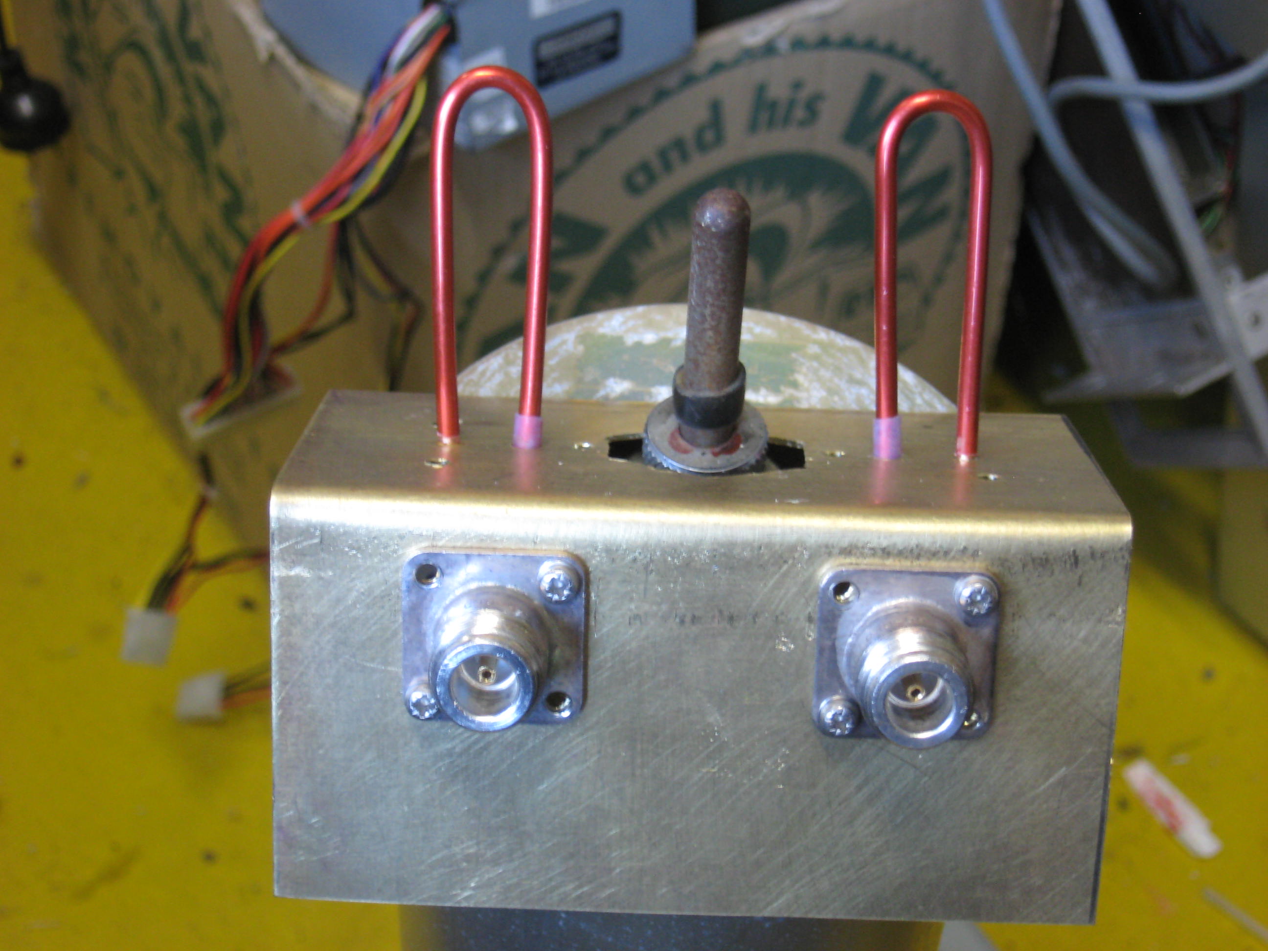
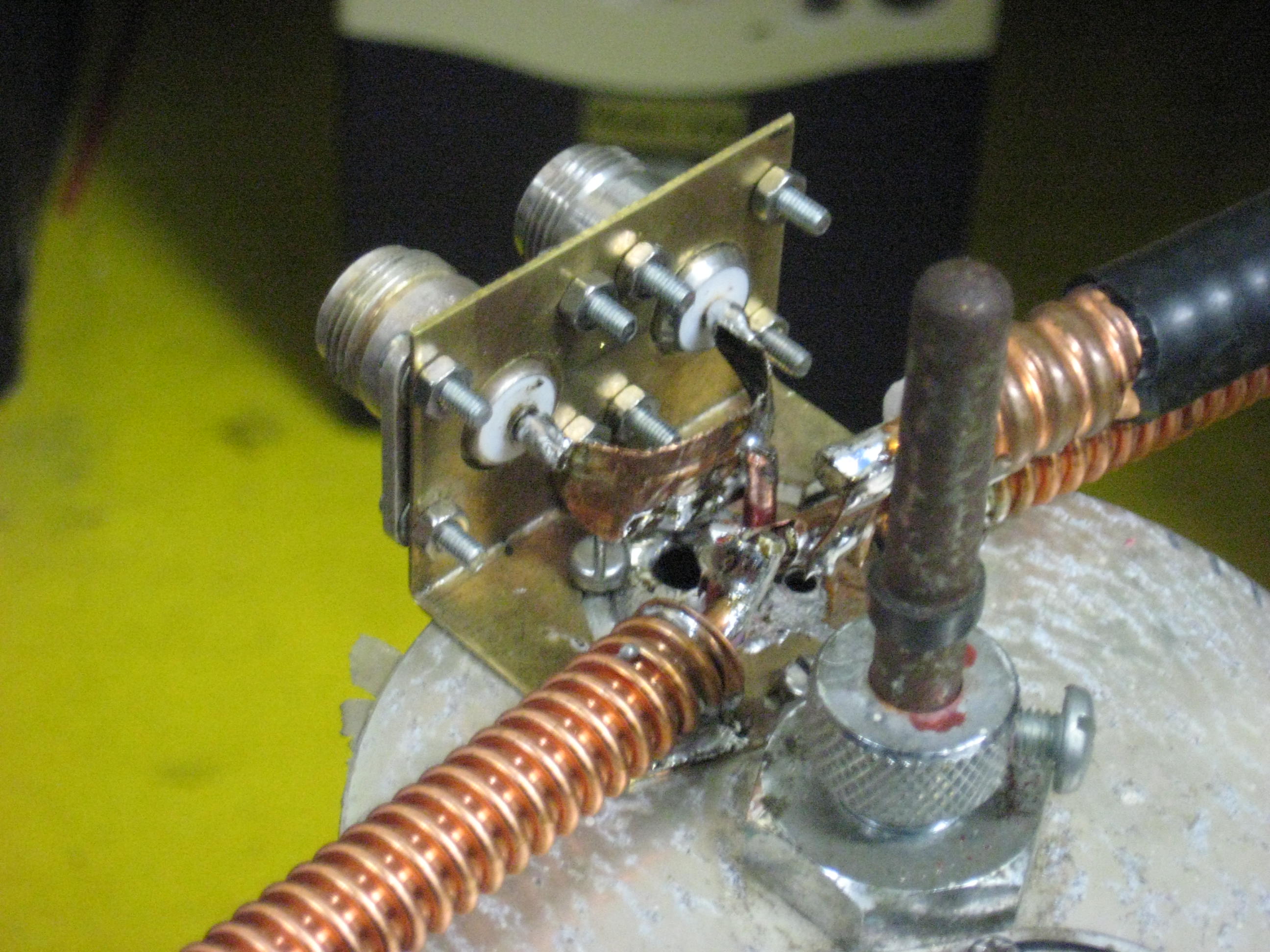
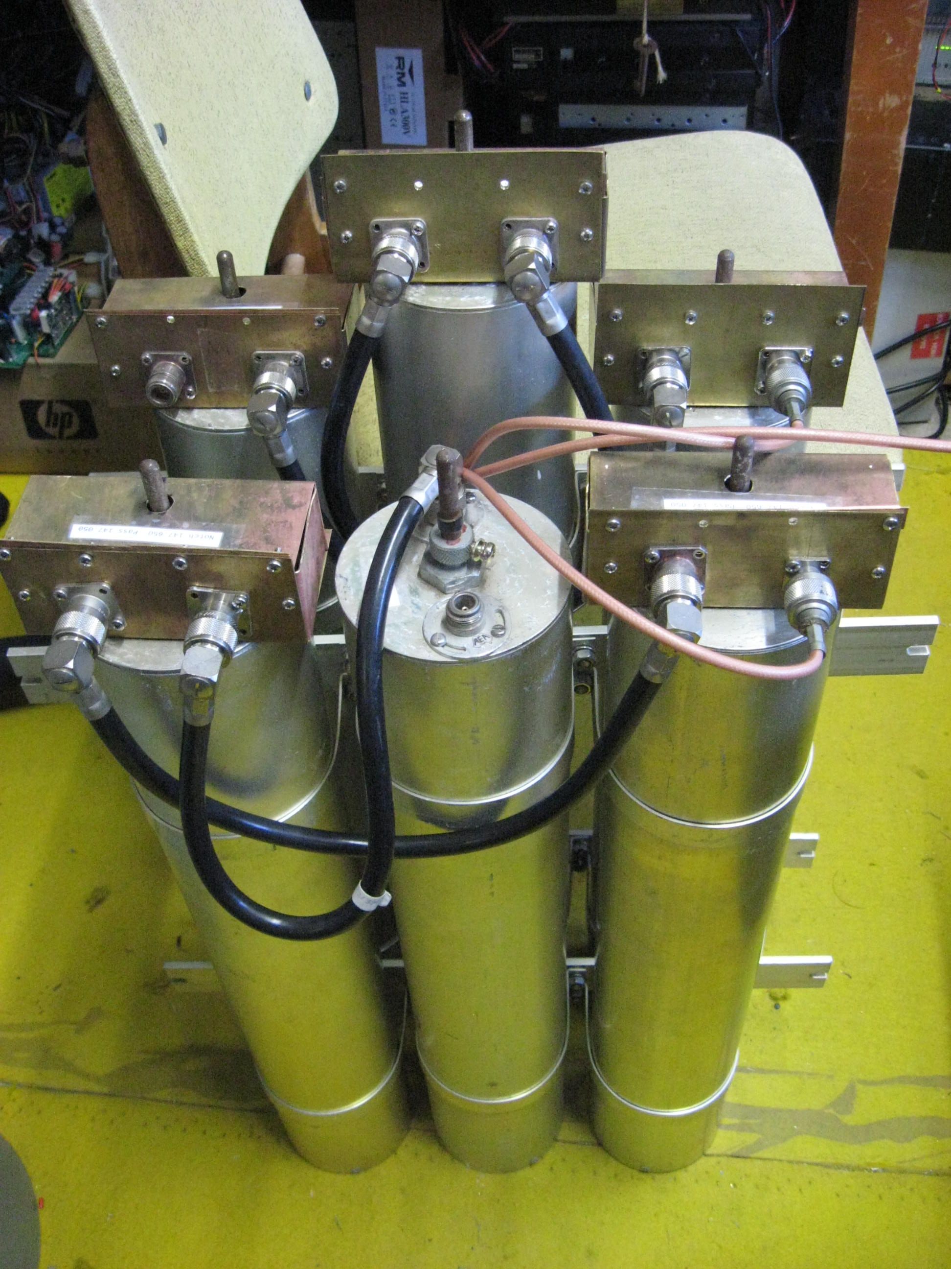
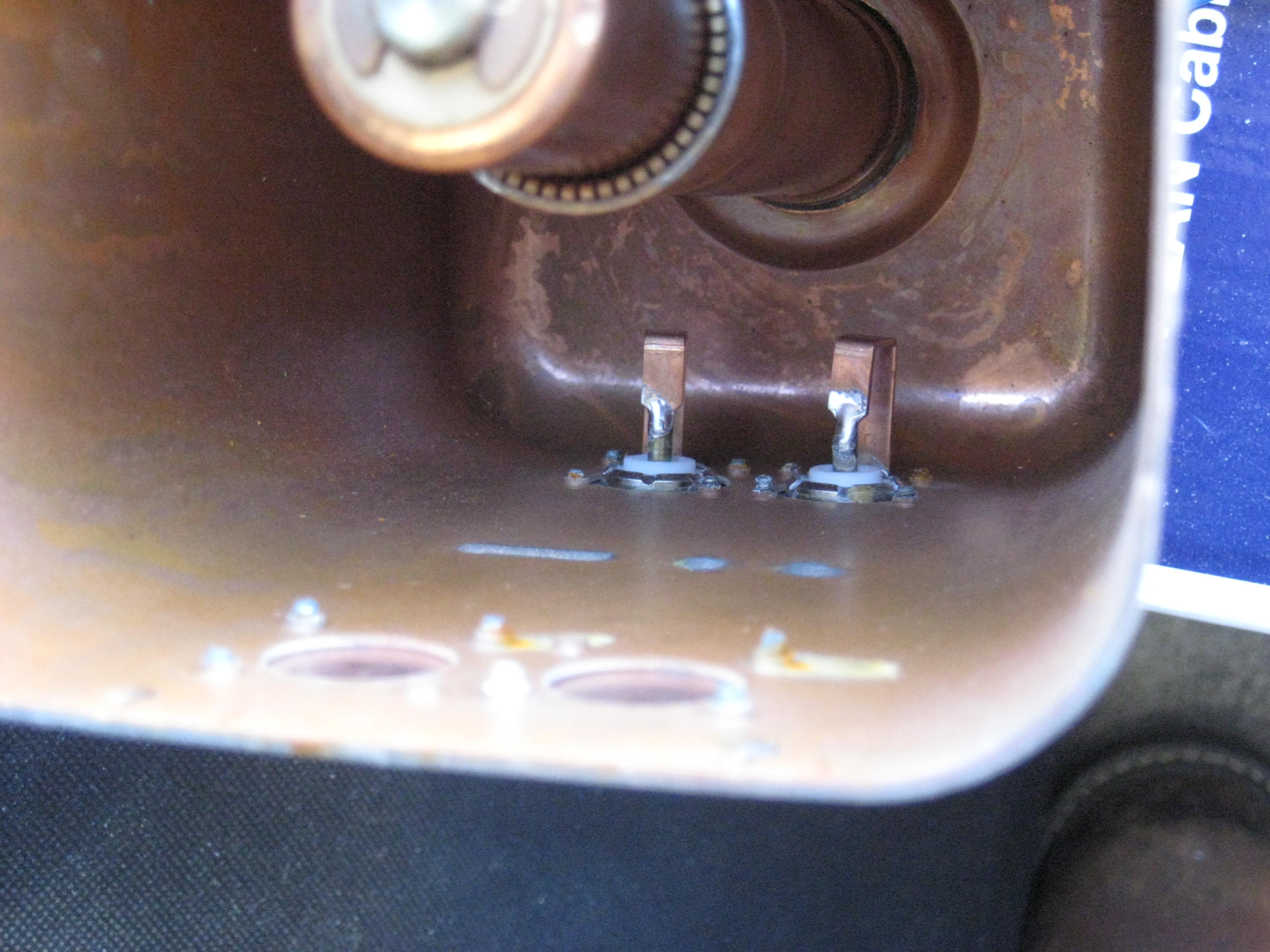
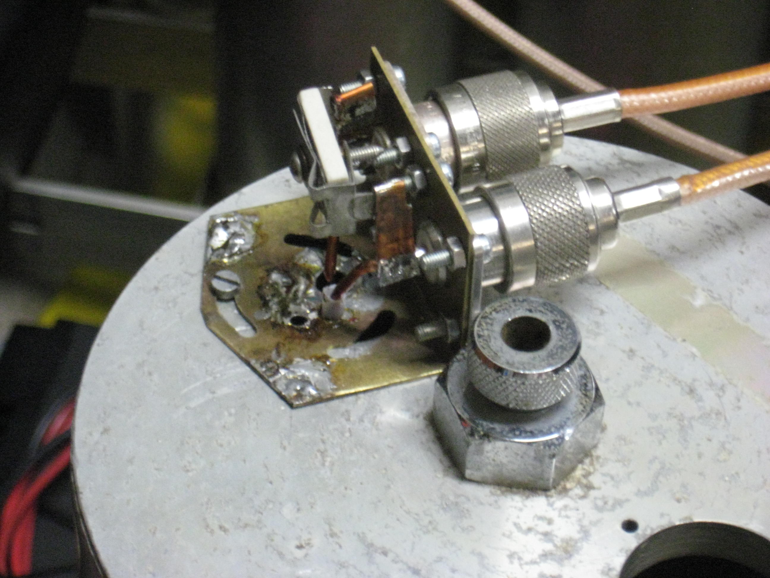
A little box with two connectors and the tuning cap, with a loop protruding
into the cavity is ideal. Make the box twist +- 30 deg. for coupling adjustment.
This changes the pass-notch spacing.
Trimmers must be GOOD eg. piston
trimmers. These series resonate your loop, on 6m or 2m.
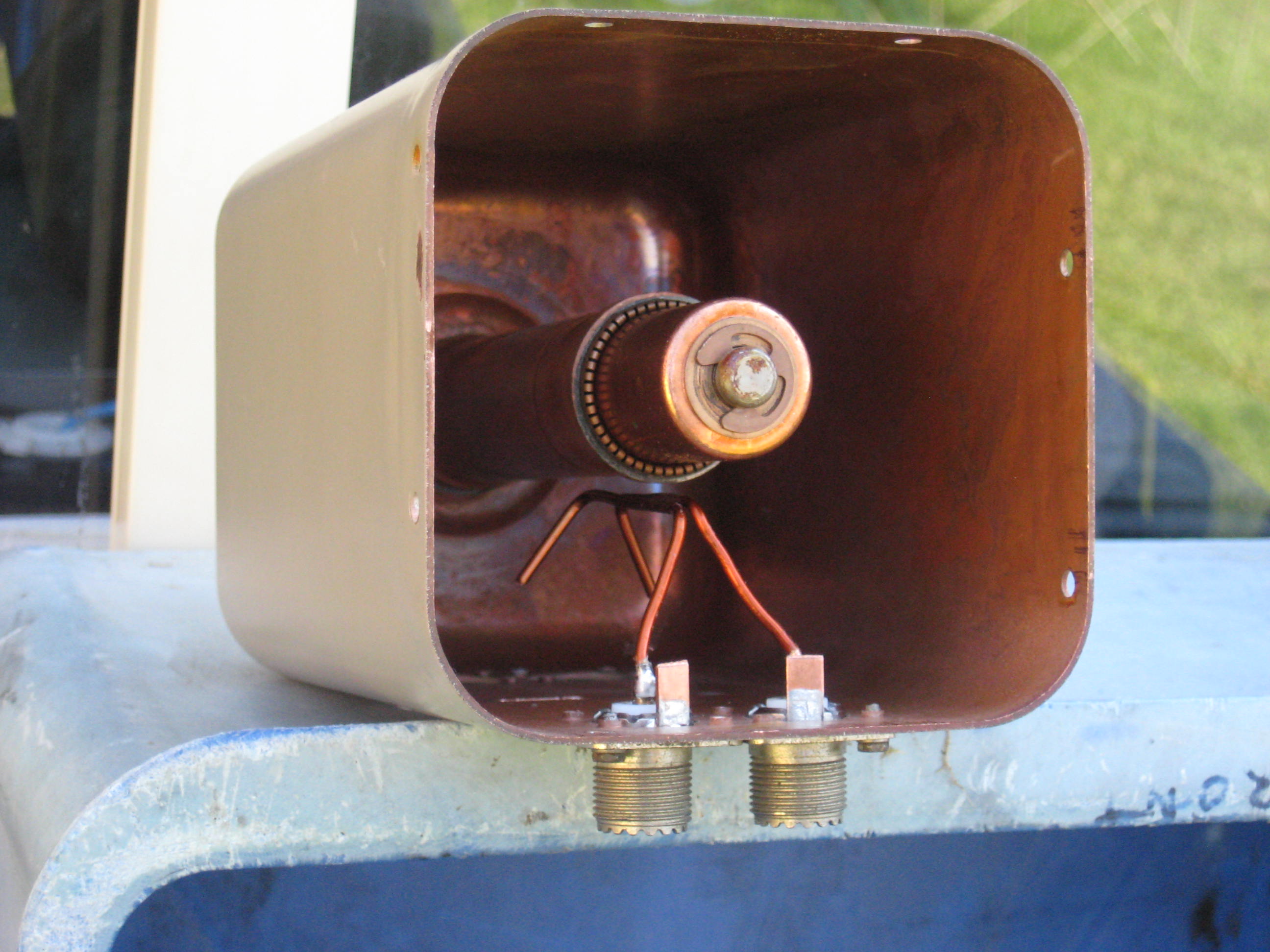
Make all this in brass or copper so all
metal parts outside the cavity have NO corrosion issues. Stainless screws.
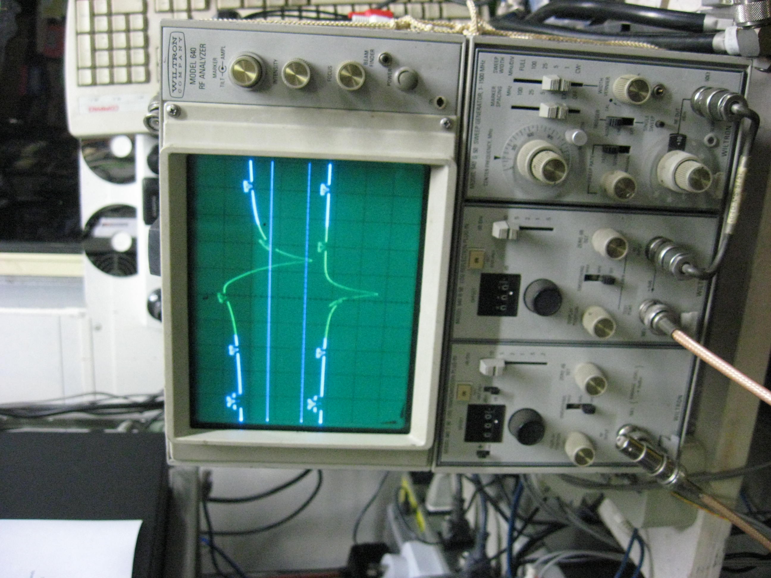
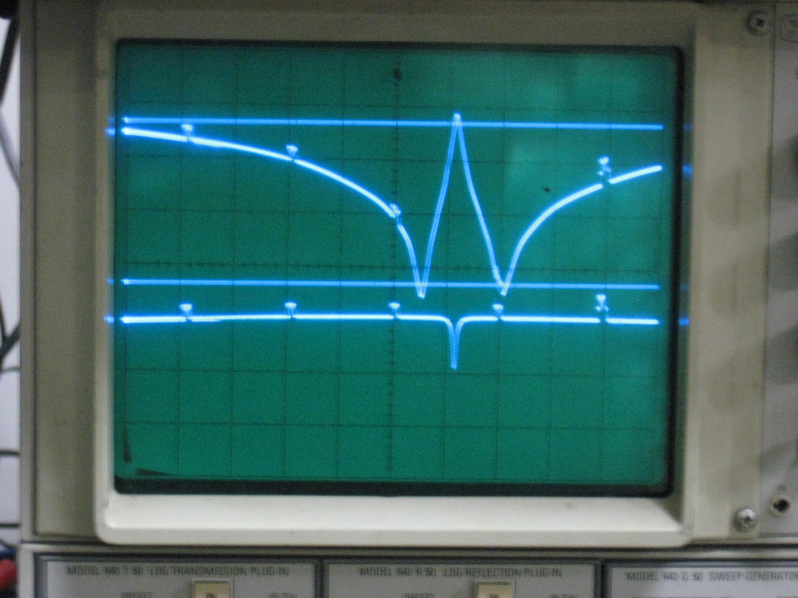
BIG Pictures. 35db notch, but only 8db down at +- 5MHz
 Feed
Feed
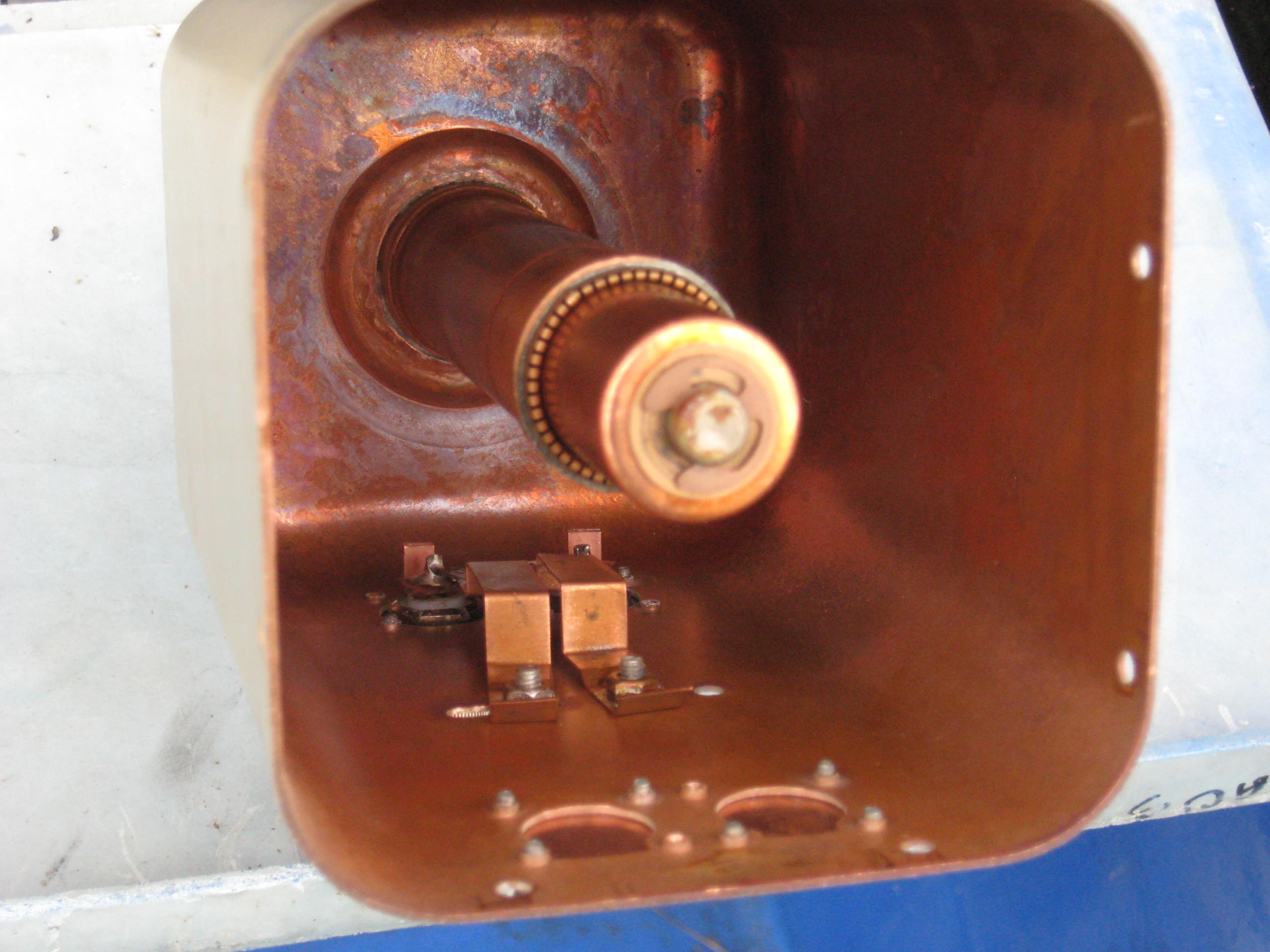
 Feed inside
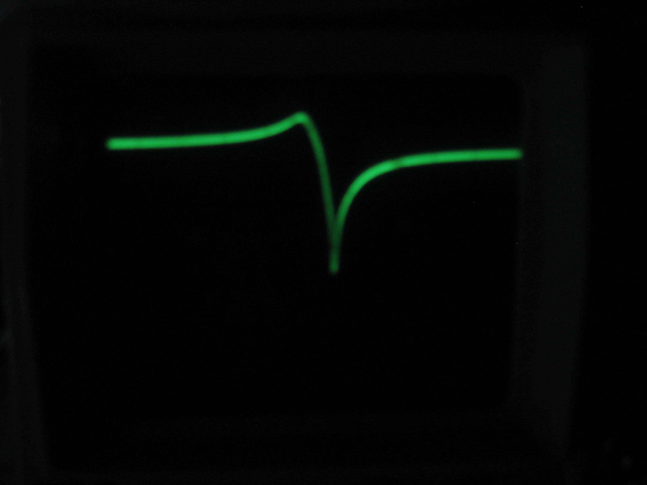 600KHz pass to notch
 IMG_3126
 IMG_3120
 IMG_3121
Notes: The two loops method has a simpler pattern, but cannot be swapped as the bypass (inductor in this case) needs to be changed to a capacitor.
My use of heliax, needs to be adjustable. Commercial cavities use expensive piston trimmers, or mechanically difficult, di-electric adjustable coaxial capacitors.
Two loops method, If I swap the phase of the 2nd loop, what happens?
 IMG_3134
 IMG_3135
 IMG_3222
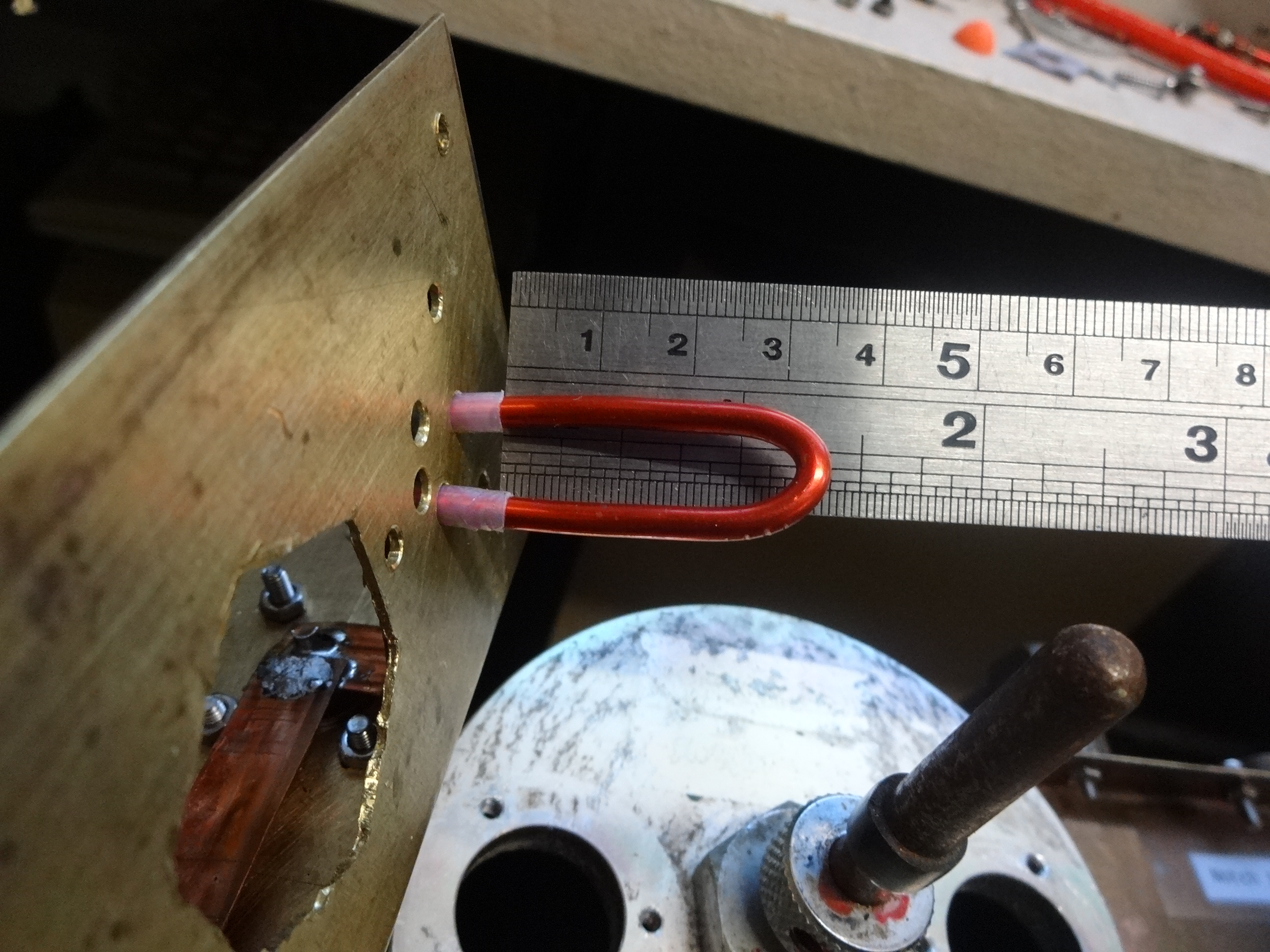
Haipin 1/8" wire 52mm long 17mm wide.
 IMG_3223
Undoing the screws, lifting the assy, I saw the pass - notch spacing reduce.
50mm hairpin is too long, even 35mm is too long, squeezed the hairpin to 13mm wide.
 IMG_3224
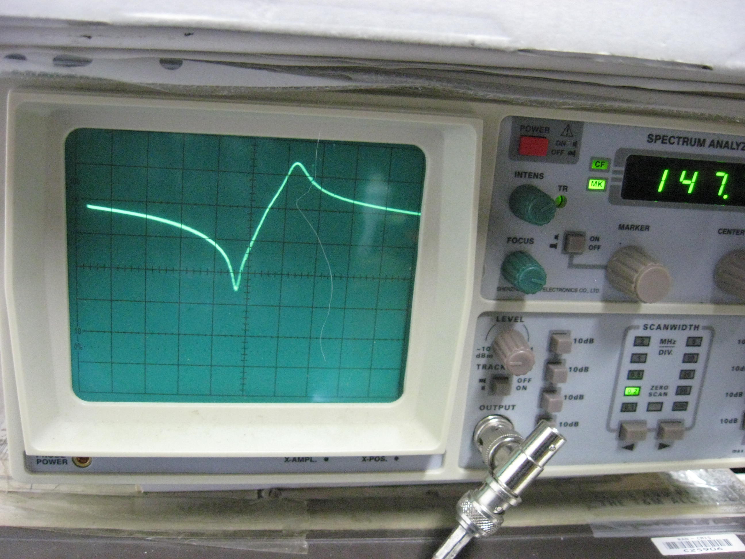
Hairpin 32mm x 13mm wide
 IMG_3225
Pass 147.050 MHz, Notch 147.650 MHz. IMG_3224 IMG_3225
Now to make the back covers.
Some people love die-cast boxes. If I could solder to them, I would too.
 IMG_3228
Consider the signal going past the T junction, say Rx. If the Tx cavity
input impedance is 0 ohm at Rx frequency, then after a 1/4 wave line, should
be infinite impedance at the T junction .:. no power lost down the Tx line.
So, what do MY cavities measure?
Tests with a Field Fox showed, no good.
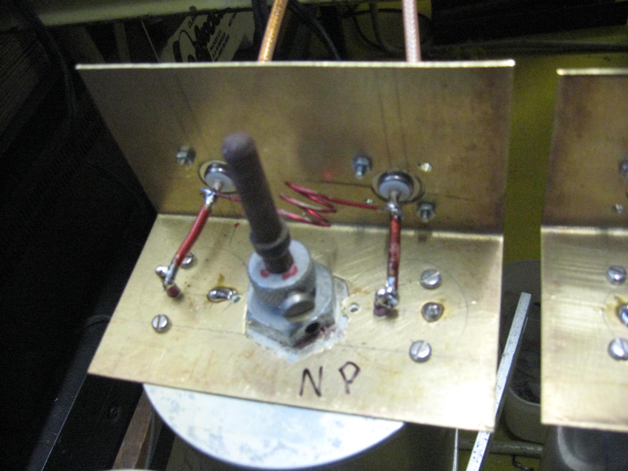
I made up a test lead, since I don't trust "T" pieces, I made one with two
RG58 cables going into an N plug. Thus making the shortest distance to the
tested "N" sockets on the cavities.
Results: Abysmal. None of my 3 Rx cavities show anywhere near 0 ohms at the
Tx frequency. Now the Tx cavities. No better.
So the theory of 1/4 wave lines from the "T" to Rx and Tx chains is in question.
Further testing needed of more cavities.
Never have I seen in the literature, other than 1/4 wave lines. See the two pixtures, top of this page.
Well, I have, in 'actual designs', cutting lengths, and was puzzled.
As it happens, I have an adjustable length coax cable by GR (General Radio)
with, of course, GR connectors!! (and adapters to "N").
Well, it WORKS. I can match, spot on, the line length needed for best SWR.
Then, I have to work out it's equivalent in 'normal' coax.
 DSC00001.JPG 35mm at 45deg hairpin 1/8" copper wire
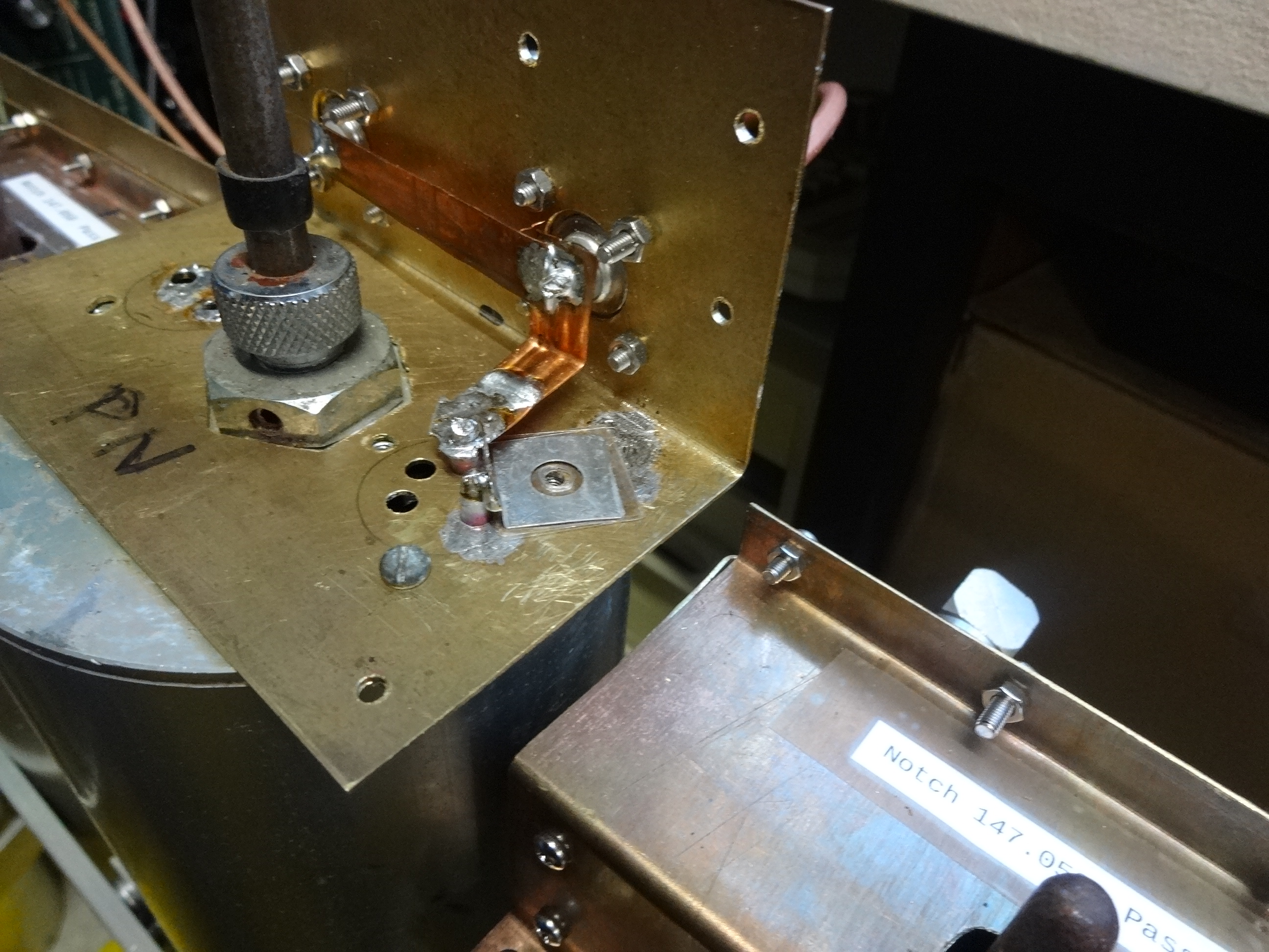 DSC00003.JPG Postage stamp trimmer plate, 5 micas under it. Held down with a 3mm perspex block.
Now at my antenna "T" I have better than 25db return loss at the notch frequency.
This means very little of my Rx signal is lost down the Tx cavity chain, and/or, the Tx signal is not
presented with a bad SWR at the antenna "T" due to the Rx cavity chain.
Was this cavity made under patent protection, and therefore, others used inferior techniques such as the "discrete component (L or C) coupling outside the cavity".
 Motorola UHF IMG_3231 Pass 434MHz, Notch 449MHz 60db deep!!
Brainwave Place the loops vertically down the cavity side therefore
swapping
the phase of the coupling magnetic field between loops and hence swapping the notch & pass.
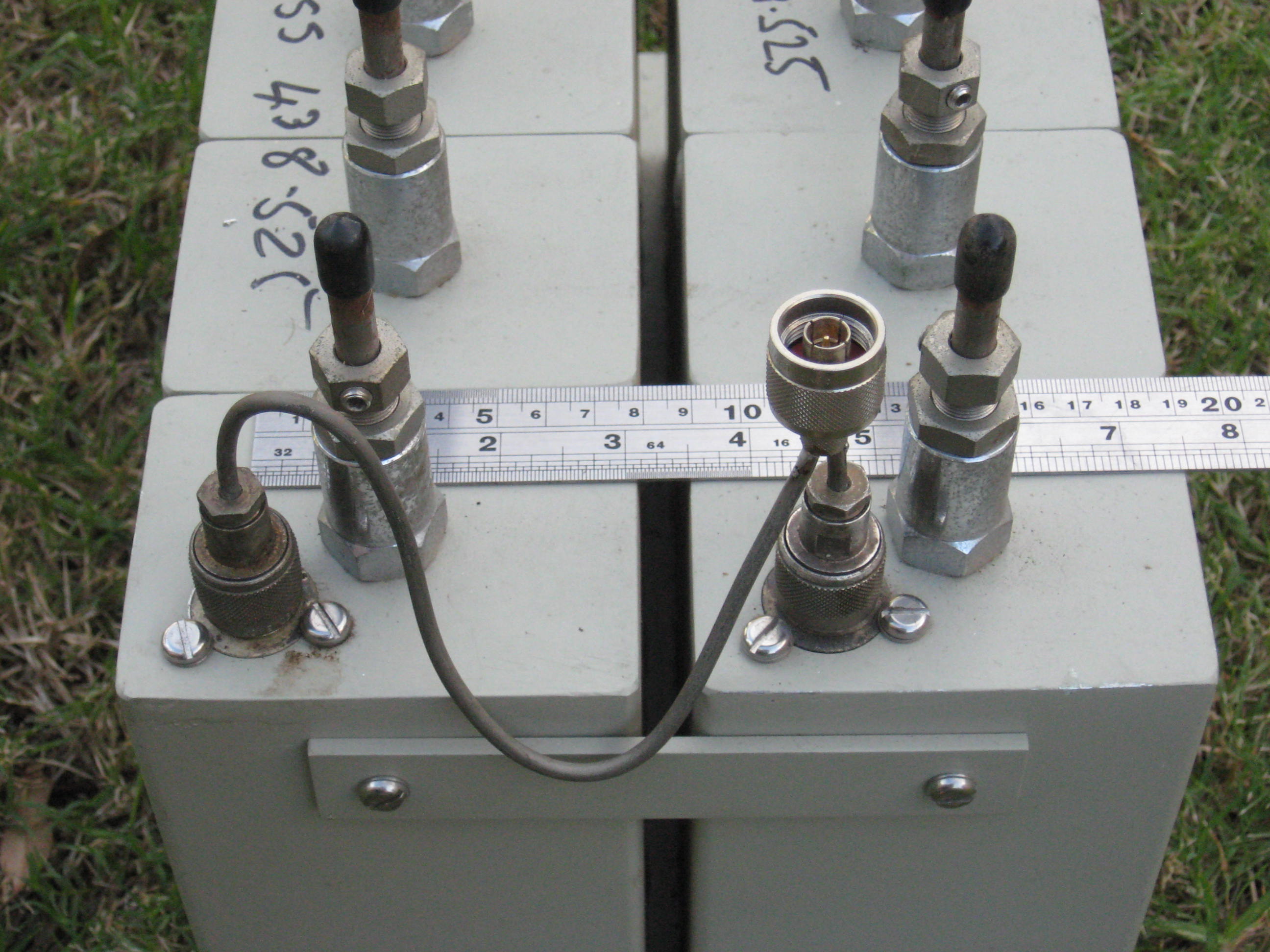
I drilled a new set of connector holes and it WORKS. 55db Notch 433MHz, pass 438.5MHz.(loops now closer, bent a bit and 5.0MHz split)
 Motorola UHF IMG_3232 ignore the label
From The Motorola doc, they didn't try this. http://www.repeater-builder.com/motorola/t1500/t1500-cavity-app-notes.pdf
http://www.cactus-intertie.org/LA/tec_not6.pdf shows their adjustable magnetic coupling.
I tried their pictured capacitance method, could barely get 50MHz split with 3mm and 2mm wire 15mm off the side-wall.
 Doesn't work.
 Superb 5MHz split etc.. 10mm strip 10mm up, 15mm along, 5mm down, 10mm to connector pin. Strip bent over at 90 deg.
The pass is quite broad.
One last method just tried, at 2m a parallel resonant circuit inside the cavity between two connectors on the cavity wall. This has an obvious advantage, at the notch frequency it is a predictable high Z, making the line to the antenna "T" a 1/2 wave. See tx-rx-instruction-manual-vari-notch-duplexers-with-6-inch-cavities.pdf May 2018, their 1/4 wave inter cavity cables are not correct!! And, neither are the line lengths to the antenna Tee.
Fundamental RF theory: With any two port device, the input impedance will depend on the output impedance. Full stop, period. So on connecting up the second cavity, EXPECT problems.
5MHz markers, then one adjusts the peak towards either notch. Same as for series resonant. Bonus, can be an Rx or Tx cavity.
My six inch 2m test cavity, was for 70MHz, I cut it in half. It had no plunger.
 A bit of work.