Wavetek 3001 Frequency Plan


Here's a frequency plan for the phase locked loops in the Wavetek 3001. This excellent effort was sent by Henk Keppel, PA0KEP, to assist those repairing the 3000 series instruments, and will certainly save folks a lot of time, and presents a much needed synopsis that isn't easily nor intuitively extracted from the detailed circuit descriptions in the manual. manual. Many thanks and a big 73 to PA0KEP!

Henk provides the following commentary for the spreadsheet:

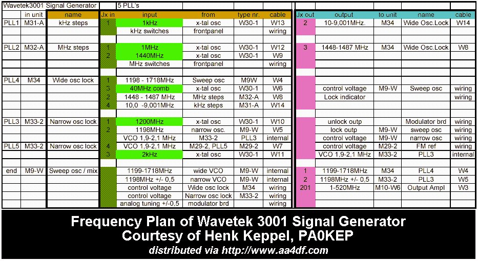
The signals from the reference oscillator are in light green, the input connectors are in dark green, and the output connectors of the units involved are in pink.

It all starts with PLL1 (the kHz steps), and continues with PLL2, the MHz steps. The outputs of both go to PLL4, the Wide Oscillator Lock.

The Wide Oscillator Lock output controls the sweep oscillator, which also contains a mixer which mixes the signals down to 0-520Mhz. From there it goes to the output amplifier.. this is the main loop.

PLL3 and 5 are for additional functions such as FM modulation and the Vernier Tuning on the front. They change the frequency of the Narrow Oscillator (VCO) which in turn also controls the Sweep Oscillator.


Dialup say 356.123MHz

We split up the 0-520MHz into 40MHz segments.
356 mod 40 => 320.
356 - 320 = 36
PLL2 (MHz) gets 36MHz from MHz switches 0-9 and tens switches 0 1 and 2.
PLL2 will be 1440 + 8 + 36 => 1484 MHz and is rough tuned 1448-1487MHz by the DAC from the MHz switches, 0-9 & tens 0, 1 and 2.
This (+8) is done by a fuse link prom taking lines 2 4 8 20 and 100.
PLL1 (KHz) gets 123KHz so, 10.000MHz - 123KHz => 9.877 MHz
PLL5 1198MHz comes from 120 x 10 (comb) - FM 2MHz.
Now the clever bit.
The Wide Oscillator, PLL4 tuned by Analog DAC from MHz 1-520, 1199 to 1718 MHz
Rough tuned now to 1554 MHz by the 356MHz switches.
is mixed with the 1484 MHz and Low Pass filtered (250MHz), 1554 - 1484 = 70 MHz
which is mixed with the 40MHz comb and LPFed (10MHz) then phase compared to the 9.877MHz of PLL1.
Next multiple of 40MHz is 80MHz so for a 9.877 output, we need 70.123 MHz and so PLL4 is actually set to 1554.123 MHz.
Now with PLL4 at 1554.123 MHz we mix it with 1198MKz to produce the final 356.123 MHz.

Frequencies less than 1MHz are done by mixing PLL1 with 10MHz.


Tuning notes

1) Many many black 10uF 25V black tantalum capicitors went short across the
+18 and -18 Volt supply lines.
2) Several MC14558 or LM558 dual op-amps failed, replaced with TL072 or LF353.

3) Be careful not to set the output level too high into your frequency counter
or you'll go mental wondering why the output frequency is wrong.

4) Levels. Several op-amps driving leveling failed. The Wide Oscillator lock
will behave poorly if the M34 Leveler TP (pin 14) is not about +2V Adjust M9W "B" often twiddled to set frequency - wrong!!.

Circuit notes
The circuits show module M172 being the "Sweep drive/DAC".
Both my 3002s have modules M2M and M22 but no M172.
M22 takes all the MHz switches and produces two outputs, 0-39MHz
which goes to PLL2, and 0-520MHz. Setup M22 precicely with a DMM.
The M2M circuit is exactly the same as the LHS of the M172 circuit.
The M22 0-520 output goes to the M2M where it is "fiddled". First set M2M output to 0.00V at 250MHz (M2M 10 turn pot) and centre M9W trimmer "A"
then adjust "300" (other 10 turn pot) then "350" "400" "450" and "500". Then go down, 100 50 and 0.


AA4DF's Yard Sale
AA4DF Home